
User`s guide
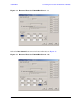
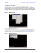
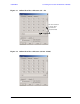

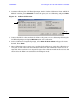

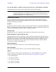
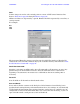
Table Of Contents
- U3042AE12
- Title Page
- TOC
- Introduction
- Description
- Available Options
- Verifying the Shipment
- General Specifications
- Typical Reflection Tracking
- Front and Rear Panel Features
- System Setup with N5230A/C
- Controlling the Test Set with N5230A
- System Setup with N5242A
- Controlling the Test Set with N5242A or N5230C
- DUT Control Lines
- Test Set I/O Interface Commands
- Operational Check
- Troubleshooting Operational Check Failures
- Service Information
- Theory of Operation
- RF Switch Components
- S100 - Source to Ports (1, 5, 9 and 13)
- S200 - Source to Ports (2, 6, 10 and 14)
- S300 - Source to Ports (3, 7, 11 and 15)
- S400 - Source to Ports (4, 8, 12 and 16)
- S101 - Receiver to Ports (1, 5, 9 and 13)
- S201 - Receiver to Ports (2, 6, 10 and 14)
- S301 - Receiver to Ports (3, 7, 11 and 15)
- S401 - Receiver to Ports (4, 8, 12 and 16)
- RF Coupler Components
- System Block Diagram
- Safety and Regulatory Information
- Electrostatic Discharge Protection
- Contacting Agilent
46 User’s Guide
U3042AE12 Controlling the Test Set with N5242A or N5230C
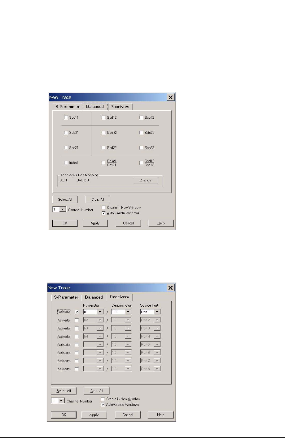
Balanced Tab: Balanced Measurements can be configured by selecting the Balance tab
in the New Measurement menu. Refer to Figure 20 on page 25.
For more information on balanced (differential) component measurement, refer to the
Application Note 1373-1 and 1373-2 (5988-5634EN and 5988-5635EN) at
http://www.home.agilent.com. In the search menu type in “Multiport and Balanced.”
Figure 40 Selecting Balanced Measurements
Receiver Tab: The S-Parameter measurements can be ratioed with selectable
Denominators for each port and receiver. Refer to the standard PNA-X documentation for
more information.
Figure 41 Receiver Measurements