
User`s guide
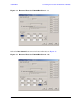
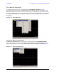
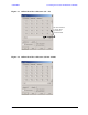

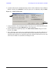

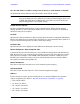
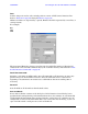
Table Of Contents
- U3042AE12
- Title Page
- TOC
- Introduction
- Description
- Available Options
- Verifying the Shipment
- General Specifications
- Typical Reflection Tracking
- Front and Rear Panel Features
- System Setup with N5230A/C
- Controlling the Test Set with N5230A
- System Setup with N5242A
- Controlling the Test Set with N5242A or N5230C
- DUT Control Lines
- Test Set I/O Interface Commands
- Operational Check
- Troubleshooting Operational Check Failures
- Service Information
- Theory of Operation
- RF Switch Components
- S100 - Source to Ports (1, 5, 9 and 13)
- S200 - Source to Ports (2, 6, 10 and 14)
- S300 - Source to Ports (3, 7, 11 and 15)
- S400 - Source to Ports (4, 8, 12 and 16)
- S101 - Receiver to Ports (1, 5, 9 and 13)
- S201 - Receiver to Ports (2, 6, 10 and 14)
- S301 - Receiver to Ports (3, 7, 11 and 15)
- S401 - Receiver to Ports (4, 8, 12 and 16)
- RF Coupler Components
- System Block Diagram
- Safety and Regulatory Information
- Electrostatic Discharge Protection
- Contacting Agilent
44 User’s Guide
U3042AE12 Controlling the Test Set with N5242A or N5230C
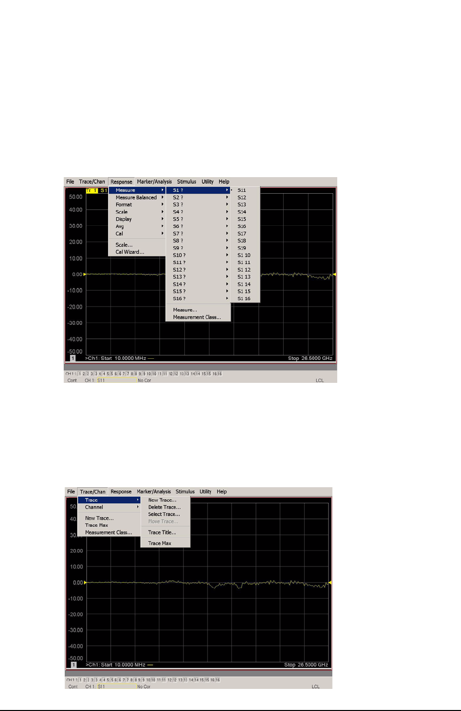
Trace Measure S-Parameter
S-Parameter selection can be accomplished using Response > Measure. Use the
drop-down menus to select 1 of 256 S-Parameters for the 16-Port system, see Figure 36.
The first number in the Sxx selection is the Receiver Port and the second number will be
the Source Port. Any port can be selected to be the Receiver, Source or both, as in S11. The
front panel R LED indicates the port is the Receiver and the S LED indicates the port is
the Source.
Figure 36 Trace Measure
New Trace Measure S-Parameter
S-Parameter Tab: Multiple S-Parameters can be made from the New Measurement
menu. In the drop-down menu select Trace > New Trace. The New Measurement window
allows the selection of any of the 256 S-Parameter's. Refer to Figure 37 and Figure 38.
Figure 37 New Trace Measure