
User`s guide
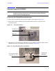
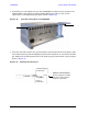
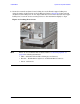
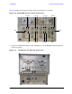
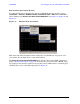
Table Of Contents
- U3042AE12
- Title Page
- TOC
- Introduction
- Description
- Available Options
- Verifying the Shipment
- General Specifications
- Typical Reflection Tracking
- Front and Rear Panel Features
- System Setup with N5230A/C
- Controlling the Test Set with N5230A
- System Setup with N5242A
- Controlling the Test Set with N5242A or N5230C
- DUT Control Lines
- Test Set I/O Interface Commands
- Operational Check
- Troubleshooting Operational Check Failures
- Service Information
- Theory of Operation
- RF Switch Components
- S100 - Source to Ports (1, 5, 9 and 13)
- S200 - Source to Ports (2, 6, 10 and 14)
- S300 - Source to Ports (3, 7, 11 and 15)
- S400 - Source to Ports (4, 8, 12 and 16)
- S101 - Receiver to Ports (1, 5, 9 and 13)
- S201 - Receiver to Ports (2, 6, 10 and 14)
- S301 - Receiver to Ports (3, 7, 11 and 15)
- S401 - Receiver to Ports (4, 8, 12 and 16)
- RF Coupler Components
- System Block Diagram
- Safety and Regulatory Information
- Electrostatic Discharge Protection
- Contacting Agilent
User’s Guide 35
U3042AE12 System Setup with N5242A
System Setup with N5242A
WARNING The opening of covers or removal of parts is likely to expose
dangerous voltages. Disconnect the instrument from all voltage
sources while it is being opened.
Preparing the N5242A Network Analyzer
1. Remove the feet from the bottom of the network analyzer. Refer to Figure 24.
2. Remove the 2 lower standoffs and screws (0515-1619) from the rear panel on the
network analyzer.
Figure 24 Rear Bottom Feet
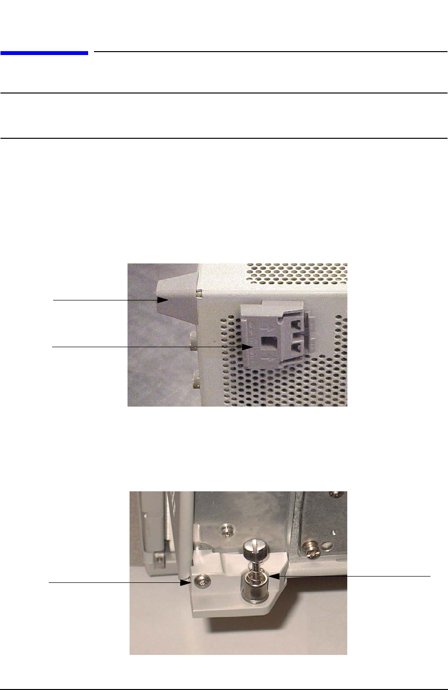
3. Install the two rear locking feet (5023-0132) onto the PNA-X, using the included screws
(0515-1619), where the standoffs were removed. Refer to Figure 25.
Figure 25 Install Locking Feet on N5242A
Standoffs (x2)
Feet (x4)
Locking Feet
(5023-0132)
Included in package
Screws (0515-1619)