
User`s guide
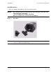
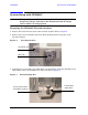
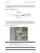
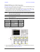
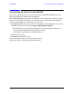
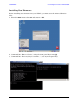
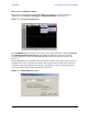
Table Of Contents
- U3042AE12
- Title Page
- TOC
- Introduction
- Description
- Available Options
- Verifying the Shipment
- General Specifications
- Typical Reflection Tracking
- Front and Rear Panel Features
- System Setup with N5230A/C
- Controlling the Test Set with N5230A
- System Setup with N5242A
- Controlling the Test Set with N5242A or N5230C
- DUT Control Lines
- Test Set I/O Interface Commands
- Operational Check
- Troubleshooting Operational Check Failures
- Service Information
- Theory of Operation
- RF Switch Components
- S100 - Source to Ports (1, 5, 9 and 13)
- S200 - Source to Ports (2, 6, 10 and 14)
- S300 - Source to Ports (3, 7, 11 and 15)
- S400 - Source to Ports (4, 8, 12 and 16)
- S101 - Receiver to Ports (1, 5, 9 and 13)
- S201 - Receiver to Ports (2, 6, 10 and 14)
- S301 - Receiver to Ports (3, 7, 11 and 15)
- S401 - Receiver to Ports (4, 8, 12 and 16)
- RF Coupler Components
- System Block Diagram
- Safety and Regulatory Information
- Electrostatic Discharge Protection
- Contacting Agilent

User’s Guide 17
U3042AE12 Controlling the Test Set with N5230A
Controlling the Test Set with N5230A
This section will describe how to setup and operate the U3042AE12 Multiport Test Set
with the N5230A 4-Port PNA-L Network Analyzer.
The U3042AE12 Multiport Test Set is considered a “slave” instrument. A PNA–L must be
used to control the Test Set. There are three methods to control the Test Set. Multiport
mode is recommended due to calibration and ease of use.
• PNA Multiport Mode firmware revision ≥ A.07.50.26 for the N5230A Option 551. From
the PNA drop-down menu and select Help > About Network Analyzer.
The following test set file must be installed into network analyzer file directory:
c:\Program Files\Agilent\Network Analyzer\testsets
4-Port PNA-L requires test set: u3042ae12_p4.tsx
• PNA Interface Control
• PNA GPIB Command Processor
Visit our website for firmware revision and downloads.
http://na.tm.agilent.com/pna/firmware/firmware.htm