
User`s guide
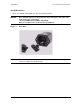
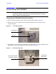
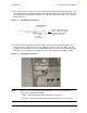
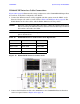
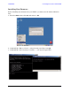
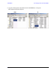
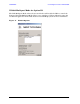
Table Of Contents
- U3042AE12
- Title Page
- TOC
- Introduction
- Description
- Available Options
- Verifying the Shipment
- General Specifications
- Typical Reflection Tracking
- Front and Rear Panel Features
- System Setup with N5230A/C
- Controlling the Test Set with N5230A
- System Setup with N5242A
- Controlling the Test Set with N5242A or N5230C
- DUT Control Lines
- Test Set I/O Interface Commands
- Operational Check
- Troubleshooting Operational Check Failures
- Service Information
- Theory of Operation
- RF Switch Components
- S100 - Source to Ports (1, 5, 9 and 13)
- S200 - Source to Ports (2, 6, 10 and 14)
- S300 - Source to Ports (3, 7, 11 and 15)
- S400 - Source to Ports (4, 8, 12 and 16)
- S101 - Receiver to Ports (1, 5, 9 and 13)
- S201 - Receiver to Ports (2, 6, 10 and 14)
- S301 - Receiver to Ports (3, 7, 11 and 15)
- S401 - Receiver to Ports (4, 8, 12 and 16)
- RF Coupler Components
- System Block Diagram
- Safety and Regulatory Information
- Electrostatic Discharge Protection
- Contacting Agilent
16 User’s Guide
U3042AE12 System Setup with N5230A/C
N5230A/C RF Interface Cable Connections
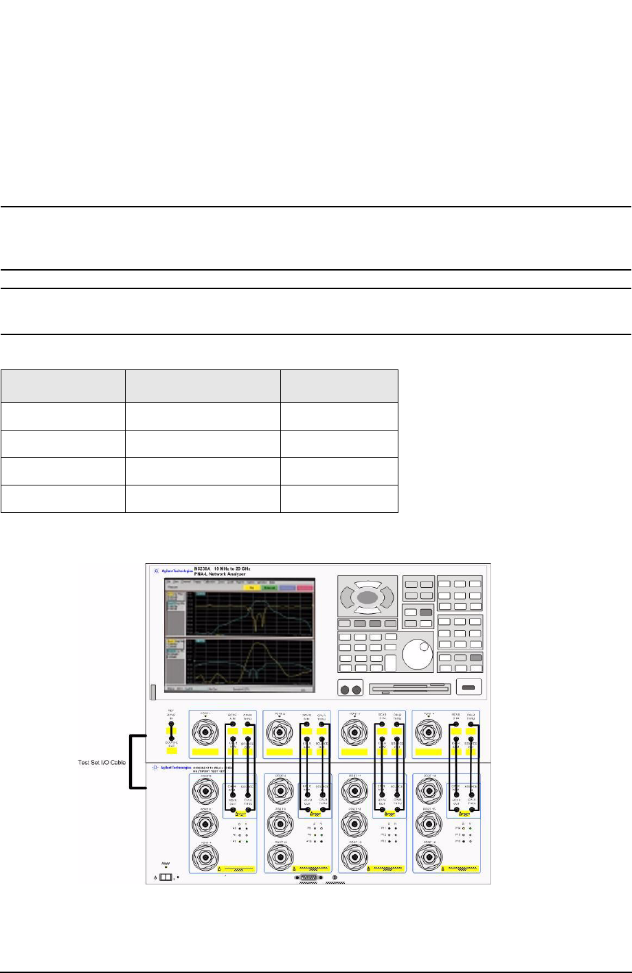
Figure 10 on page 16 illustrates the setup configuration of the U3042AE12 Multiport Test
Set and how it should be configured to the PNA-L.
1. Connect the RF interconnect cables, supplied with this option, from the PNA-L to the
Test Set. Torque each cable to 8 in-lb. Refer to Table 10 and Figure 10 on page 16. The
Z5623-20418 are the short cables and the Z5623-20419 are the long cables.
CAUTION Each end of the interconnect RF cables have a different length from the bend.
When connecting the RF Interconnect cables be sure that the longer end from
the bend is connected to the PNA.
CAUTION Over torque will cause damage to the test set and may cause connectors to
spin or become loose.
Figure 10 N5230A/C RF Interface Connections
2. Connect the PNA Test Set I/O cable (8120-6818) to the U3042AE12 Test Set Interface
on the rear panel. Refer to Figure 30 on page 39.
Table 10 N5230A/C Interface Cable Connection (Option 016)
RF Cables From PNA-L To Test Set
Z5623-20418 SOURCE OUT SOURCE OUT
Z5623-20418 CPLR ARM CPLR ARM
Z5623-20419 CPLR THRU CPLR THRU
Z5623-20419 RCVR IN RCVR OUT