
User`s guide
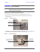
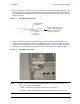
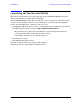
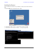
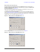
Table Of Contents
- U3042AE12
- Title Page
- TOC
- Introduction
- Description
- Available Options
- Verifying the Shipment
- General Specifications
- Typical Reflection Tracking
- Front and Rear Panel Features
- System Setup with N5230A/C
- Controlling the Test Set with N5230A
- System Setup with N5242A
- Controlling the Test Set with N5242A or N5230C
- DUT Control Lines
- Test Set I/O Interface Commands
- Operational Check
- Troubleshooting Operational Check Failures
- Service Information
- Theory of Operation
- RF Switch Components
- S100 - Source to Ports (1, 5, 9 and 13)
- S200 - Source to Ports (2, 6, 10 and 14)
- S300 - Source to Ports (3, 7, 11 and 15)
- S400 - Source to Ports (4, 8, 12 and 16)
- S101 - Receiver to Ports (1, 5, 9 and 13)
- S201 - Receiver to Ports (2, 6, 10 and 14)
- S301 - Receiver to Ports (3, 7, 11 and 15)
- S401 - Receiver to Ports (4, 8, 12 and 16)
- RF Coupler Components
- System Block Diagram
- Safety and Regulatory Information
- Electrostatic Discharge Protection
- Contacting Agilent
User’s Guide 15
U3042AE12 System Setup with N5230A/C
4. Place the network analyzer on top of the Test Set and ensure that the front frame of the
network analyzer is positioned slightly forward of the locks that are attached to the Test
Set. Slide the network analyzer back so the locks engage the front frame of the analyzer.
Refer to Figure 8.
Figure 8 Locking the Analyzer’s
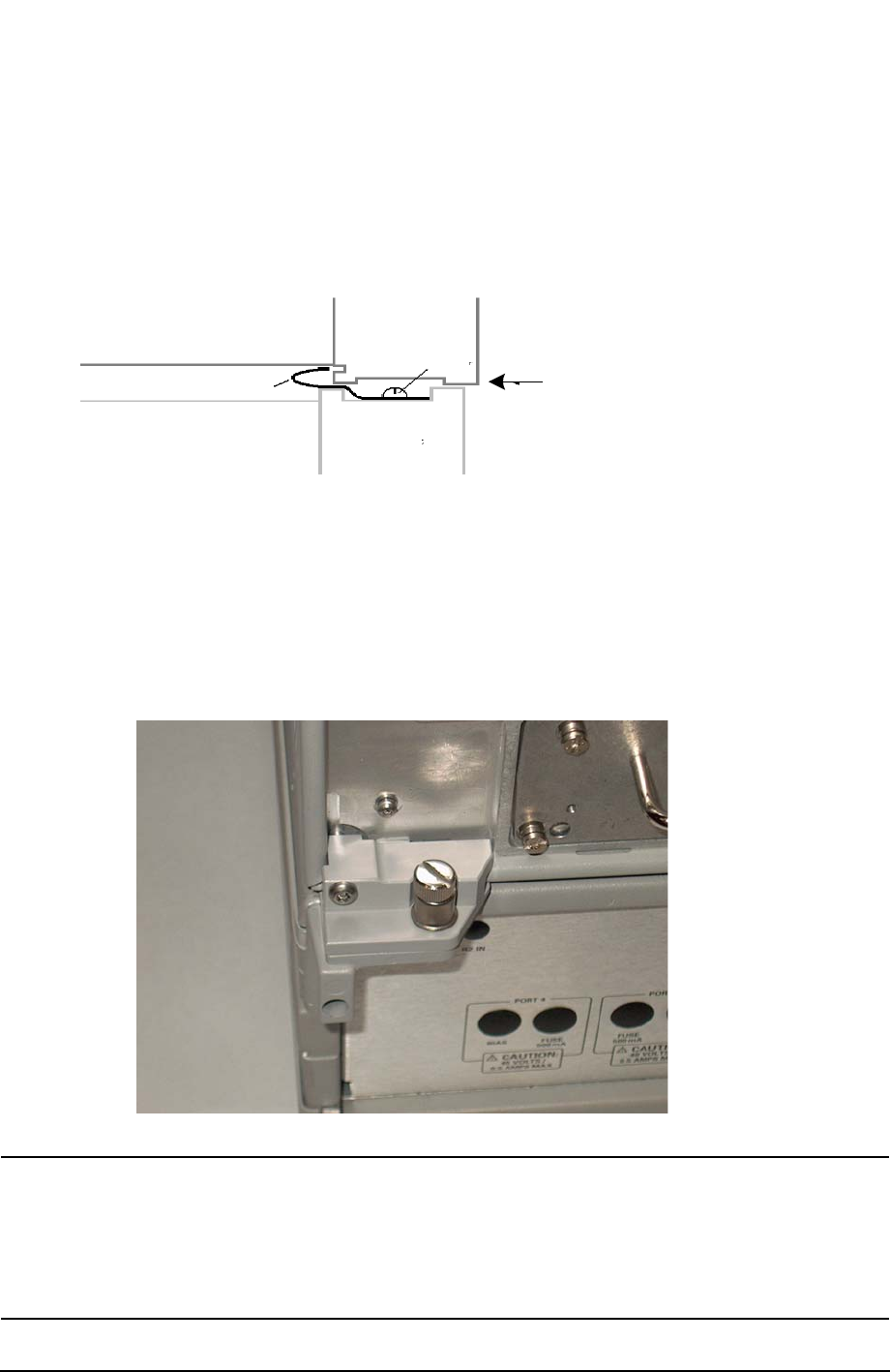
5. Secure the network analyzer’s lower locking feet to the Test Set upper locking feet,
using the spring–loaded screws on the locking feet. Refer to Figure 9. If the network
analyzer's lower locking feet are not aligned with the screw holes in the Test Set's upper
locking feet, loosen the screws securing the feet to the instrument slightly to align.
Figure 9 Locking Feet Screws
NOTE There are two Lock-Feet kits available. Refer to “Contacting Agilent” on
page 94 for ordering information.
•PNA − 5023-0132 (Kit includes locking feet and screws)
•Test Set − 5063-9253 (Kit includes lock links, locking feet and screws)
Test Set
Front Frame
Network Analyzer
Front Frame
Slide the network Analyzer
back to engage the lock link
in the back of the network
analyzer's front frame
Lock Link
screw