
User`s guide
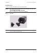
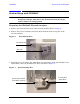
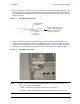
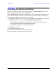
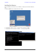
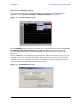
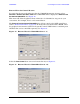
Table Of Contents
- U3042AE12
- Title Page
- TOC
- Introduction
- Description
- Available Options
- Verifying the Shipment
- General Specifications
- Typical Reflection Tracking
- Front and Rear Panel Features
- System Setup with N5230A/C
- Controlling the Test Set with N5230A
- System Setup with N5242A
- Controlling the Test Set with N5242A or N5230C
- DUT Control Lines
- Test Set I/O Interface Commands
- Operational Check
- Troubleshooting Operational Check Failures
- Service Information
- Theory of Operation
- RF Switch Components
- S100 - Source to Ports (1, 5, 9 and 13)
- S200 - Source to Ports (2, 6, 10 and 14)
- S300 - Source to Ports (3, 7, 11 and 15)
- S400 - Source to Ports (4, 8, 12 and 16)
- S101 - Receiver to Ports (1, 5, 9 and 13)
- S201 - Receiver to Ports (2, 6, 10 and 14)
- S301 - Receiver to Ports (3, 7, 11 and 15)
- S401 - Receiver to Ports (4, 8, 12 and 16)
- RF Coupler Components
- System Block Diagram
- Safety and Regulatory Information
- Electrostatic Discharge Protection
- Contacting Agilent
14 User’s Guide
U3042AE12 System Setup with N5230A/C
System Setup with N5230A/C
WARNING The opening of covers or removal of parts is likely to expose
dangerous voltages. Disconnect the instrument from all voltage
sources while it is being opened.
Preparing the N5230A/C Network Analyzer
1. Remove the feet from the bottom of the network analyzer. Refer to Figure 6.
2. Remove the 2 lower standoffs and screws (0515-1619) from the rear panel on the
network analyzer.
Figure 6 Rear Bottom Feet
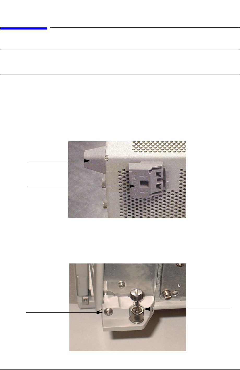
3. Install the two rear locking feet (5023-0132) onto the PNA-L, using the included screws
(0515-1619), where the standoffs were removed. Refer to Figure 7.
Figure 7 Install Locking Feet
Standoffs (x2)
Feet (x4)
Locking Feet
(5023-0132)
Included in package
Screws (0515-1619)