
User`s guide
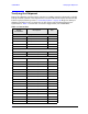
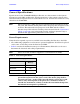
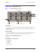
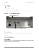
Table Of Contents
- U3042AE12
- Title Page
- TOC
- Introduction
- Description
- Available Options
- Verifying the Shipment
- General Specifications
- Typical Reflection Tracking
- Front and Rear Panel Features
- System Setup with N5230A/C
- Controlling the Test Set with N5230A
- System Setup with N5242A
- Controlling the Test Set with N5242A or N5230C
- DUT Control Lines
- Test Set I/O Interface Commands
- Operational Check
- Troubleshooting Operational Check Failures
- Service Information
- Theory of Operation
- RF Switch Components
- S100 - Source to Ports (1, 5, 9 and 13)
- S200 - Source to Ports (2, 6, 10 and 14)
- S300 - Source to Ports (3, 7, 11 and 15)
- S400 - Source to Ports (4, 8, 12 and 16)
- S101 - Receiver to Ports (1, 5, 9 and 13)
- S201 - Receiver to Ports (2, 6, 10 and 14)
- S301 - Receiver to Ports (3, 7, 11 and 15)
- S401 - Receiver to Ports (4, 8, 12 and 16)
- RF Coupler Components
- System Block Diagram
- Safety and Regulatory Information
- Electrostatic Discharge Protection
- Contacting Agilent
12 User’s Guide
U3042AE12 Front and Rear Panel Features
Line Switch
– Standby
| – ON (Active LED On)
Control Lines and Voltage Adjust
For further information pertaining to control lines and voltage adjustments see “DUT
Control Lines” on page 56.
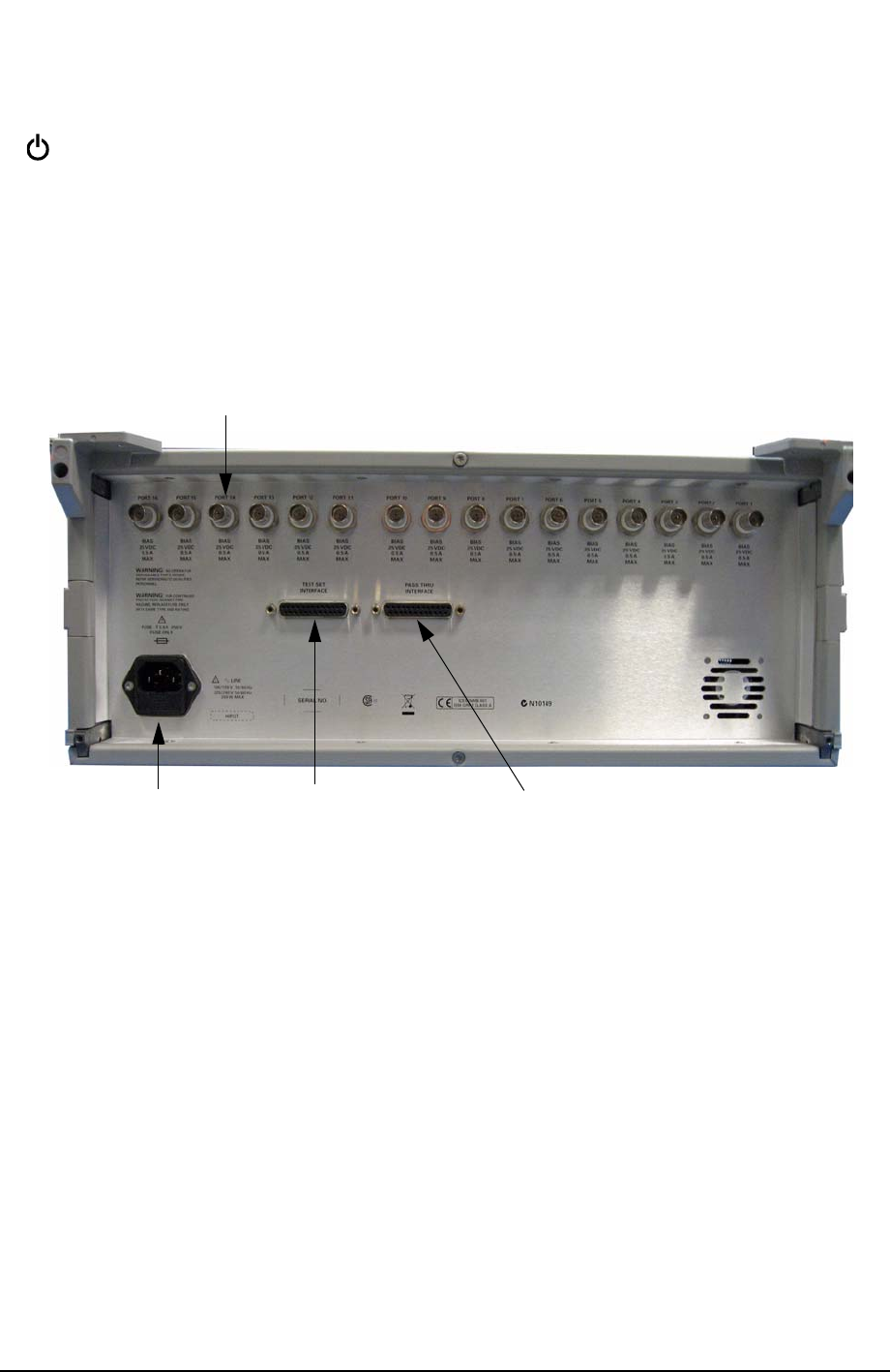
Figure 4 Rear Panel (Multiport Test Set)
Test Set Interface
The Test Set Interface connector is used to send address and data to the test set from the
PNA.
Pass Through Interface
Connection to another test set.
Line Module
The line fuse, as well as a spare, reside within the line module. Figure 5 illustrates where
the fuses are located and how to access them.
Line Module Test Set Interface Pass Through Interface
Bias Tee Input (Option 002)