
User`s guide
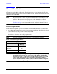
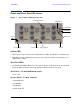
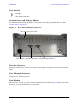
Table Of Contents
- U3042AE12
- Title Page
- TOC
- Introduction
- Description
- Available Options
- Verifying the Shipment
- General Specifications
- Typical Reflection Tracking
- Front and Rear Panel Features
- System Setup with N5230A/C
- Controlling the Test Set with N5230A
- System Setup with N5242A
- Controlling the Test Set with N5242A or N5230C
- DUT Control Lines
- Test Set I/O Interface Commands
- Operational Check
- Troubleshooting Operational Check Failures
- Service Information
- Theory of Operation
- RF Switch Components
- S100 - Source to Ports (1, 5, 9 and 13)
- S200 - Source to Ports (2, 6, 10 and 14)
- S300 - Source to Ports (3, 7, 11 and 15)
- S400 - Source to Ports (4, 8, 12 and 16)
- S101 - Receiver to Ports (1, 5, 9 and 13)
- S201 - Receiver to Ports (2, 6, 10 and 14)
- S301 - Receiver to Ports (3, 7, 11 and 15)
- S401 - Receiver to Ports (4, 8, 12 and 16)
- RF Coupler Components
- System Block Diagram
- Safety and Regulatory Information
- Electrostatic Discharge Protection
- Contacting Agilent
User’s Guide 11
U3042AE12 Front and Rear Panel Features
Front and Rear Panel Features
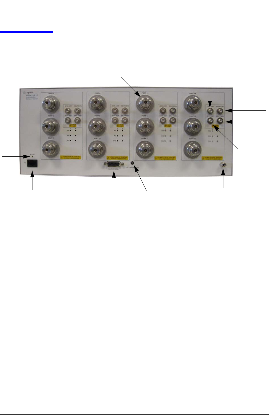
Figure 3 Front Panel (Multiport Test Set)
Active LED
• When the test set is connected and addressed by a PNA, the LED is On (illuminated).
• The LED is Off (not illuminated) when the test set power switch is in Standby, or not
addressed by a PNA.
Test Port LEDs
• An illuminated LED indicates an active port in Source or Receiver mode. On the front
panel “S” indicates Source test ports and “R” indicates Receiver test ports.
Test Ports – 3.5 mm Bulkhead (male)
• Port 5–16
Access Ports – 3.5 mm (female)
• SOURCE OUT
•
CPLR THRU
• CPLR ARM
• RCVR (A-D) IN
1 of 12 Test Ports
CPLR ARM
CPLR THRU
SOURCE IN
RCVR OUT
Control Lines
Voltage Adjust
Power Switch
Ground
Active
LED