
User`s guide
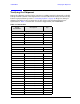
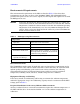
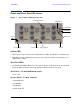
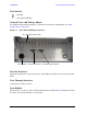
Table Of Contents
- U3042AE12
- Title Page
- TOC
- Introduction
- Description
- Available Options
- Verifying the Shipment
- General Specifications
- Typical Reflection Tracking
- Front and Rear Panel Features
- System Setup with N5230A/C
- Controlling the Test Set with N5230A
- System Setup with N5242A
- Controlling the Test Set with N5242A or N5230C
- DUT Control Lines
- Test Set I/O Interface Commands
- Operational Check
- Troubleshooting Operational Check Failures
- Service Information
- Theory of Operation
- RF Switch Components
- S100 - Source to Ports (1, 5, 9 and 13)
- S200 - Source to Ports (2, 6, 10 and 14)
- S300 - Source to Ports (3, 7, 11 and 15)
- S400 - Source to Ports (4, 8, 12 and 16)
- S101 - Receiver to Ports (1, 5, 9 and 13)
- S201 - Receiver to Ports (2, 6, 10 and 14)
- S301 - Receiver to Ports (3, 7, 11 and 15)
- S401 - Receiver to Ports (4, 8, 12 and 16)
- RF Coupler Components
- System Block Diagram
- Safety and Regulatory Information
- Electrostatic Discharge Protection
- Contacting Agilent
6 User’s Guide
U3042AE12 General Specifications
General Specifications
Specifications for the U3042AE12 Multiport Test Set are characteristic for the System
performance of the PNA and Test Set. Actual performance of the system is based on the
customers PNA and options that are used with the test set. A functional certificate is only
offered for the U3042AE12.
NOTE When connected to a PNA, this test set will degrade the performance at the
test ports. The internal switch paths reduce test port power and power to the
receivers. This affects the test port power of the PNA and also reduces
dynamic range. The reflection tracking values measured in the “Operational
Check” on page 66 can be subtracted from the analyzers dynamic range to
determine the approximate performance of the system.
Power Requirements
Verify that the required ac power is available before installing the Test Set to the PNA.
• Air conditioning equipment (or other motor–operated equipment) should not be placed
on the same ac line that powers the Test Set and PNA.
• Table 2 contains the maximum wattage for all instruments. This table can be use to
determine the electrical and cooling requirements.
NOTE Values are based on 120 Vac supplied to each instrument at 60 Hz.
WARNING This is a Safety Class I product (provided with a protective earthing
ground incorporated in the power cord). The mains plug shall be
inserted only into a socket outlet provided with a protective earth
contact. Any interruption of the protective conductor, inside or
outside the instrument, is likely to make the instrument dangerous.
Intentional interruption is prohibited.
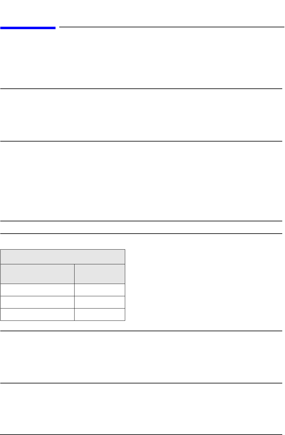
Table 2 Power Requirements
Standard Equipment
Instrument Maximum
Wattage
N5242A 270
N5230A/C 350
U3042AE12 350