Agilent Technologies U3042AE12 User’s Guide Use this manual with the following documents: PNA Series Network Analyzer On-line Help System and Application Note 1408-12 Manufacturing Part Number: U3042-90001 Printed in USA: March 2009 Supersede April 2008 © Copyright 2007- 2009 Agilent Technologies, Inc. All rights reserved.
Warranty Statement THE MATERIAL CONTAINED IN THIS DOCUMENT IS PROVIDED “AS IS,” AND IS SUBJECT TO BEING CHANGED, WITHOUT NOTICE, IN FUTURE EDITIONS. FURTHER, TO THE MAXIMUM EXTENT PERMITTED BY APPLICABLE LAW, AGILENT DISCLAIMS ALL WARRANTIES, EITHER EXPRESS OR IMPLIED WITH REGARD TO THIS MANUAL AND ANY INFORMATION CONTAINED HEREIN, INCLUDING BUT NOT LIMITED TO THE IMPLIED WARRANTIES OF MERCHANTABILITY AND FITNESS FOR A PARTICULAR PURPOSE.
Safety Notes The following safety notes are used throughout this document. Familiarize yourself with each of these notes and its meaning before performing any of the procedures in this document. WARNING Warning denotes a hazard. It calls attention to a procedure which, if not correctly performed or adhered to, could result in injury or loss of life. Do not proceed beyond a warning note until the indicated conditions are fully understood and met. CAUTION Caution denotes a hazard.
iv User’s Guide
Contents U3042AE12 Introduction . . . . . . . . . . . . . . . . . . . . . . . . . . . . . . . . . . . . . . . . . . . . . . . . . . . . . . . . . . . . . . . . . 2 Description . . . . . . . . . . . . . . . . . . . . . . . . . . . . . . . . . . . . . . . . . . . . . . . . . . . . . . . . . . . . . . . . . . 3 Network Analyzer Requirement. . . . . . . . . . . . . . . . . . . . . . . . . . . . . . . . . . . . . . . . . . . . . . . . 3 Available Options . . . . . . . . . . . . . . . . . . . . . . . . . . . . .
Contents System Setup with N5242A . . . . . . . . . . . . . . . . . . . . . . . . . . . . . . . . . . . . . . . . . . . . . . . . . . . .35 Preparing the N5242A Network Analyzer . . . . . . . . . . . . . . . . . . . . . . . . . . . . . . . . . . . . . . .35 N5242A RF Interface Cable Connections . . . . . . . . . . . . . . . . . . . . . . . . . . . . . . . . . . . . . . .38 Controlling the Test Set with N5242A or N5230C . . . . . . . . . . . . . . . . . . . . . . . . . . . . . . . . . .
Contents Safety and Regulatory Information. . . . . . . . . . . . . . . . . . . . . . . . . . . . . . . . . . . . . . . . . . . . . . Introduction. . . . . . . . . . . . . . . . . . . . . . . . . . . . . . . . . . . . . . . . . . . . . . . . . . . . . . . . . . . . . . . Before Applying Power . . . . . . . . . . . . . . . . . . . . . . . . . . . . . . . . . . . . . . . . . . . . . . . . . . . . . . Connector Care and Cleaning . . . . . . . . . . . . . . . . . . . . . . . . . . . . . . . . . . . . . . . . .
Contents Contents-4
U3042AE12 User’s Guide 1
U3042AE12 Introduction Introduction This document describes how to use the U3042AE12 Multiport Test Set with the Agilent N5230A/C 4-Port PNA-L Network Analyzer and the N5242A PNA-X for a 16-Port network analyzer solution.
U3042AE12 Description Description The Agilent U3042AE12 Multiport Test Set is a 12-Port solid-state extension test set. When combined with a 4-Port N5230A/C PNA-L or N5242A PNA-X Network Analyzer, the U3042AE12 provides a complete solution for 16-Port full crossbar measurements. The test set is directly controlled by the network analyzer, no external personal computer or software is required.
U3042AE12 Available Options Available Options Test Set Options The U3042AE12 has three available test set options: Refer to “System Block Diagram” beginning on page 85. • Standard - solid state switches for fast switch speed and improved switch life. (No Option 001 or 002 on the serial tag). • Option 001 solid state switches with amplifiers to improve dynamic range. • Option 002 solid state switches with amplifiers and bias-tees for each port.
U3042AE12 Verifying the Shipment Verifying the Shipment Inspect the shipping container. If the container or packing material is damaged, it should be kept until the contents of the shipment have been checked mechanically and electrically. If there is physical damage refer to “Contacting Agilent” on page 94. Keep the damaged shipping materials (if any) for inspection by the carrier and an Agilent Technologies representative. Table 1 contains the accessories shipped with your U3042AE12.
U3042AE12 General Specifications General Specifications Specifications for the U3042AE12 Multiport Test Set are characteristic for the System performance of the PNA and Test Set. Actual performance of the system is based on the customers PNA and options that are used with the test set. A functional certificate is only offered for the U3042AE12. When connected to a PNA, this test set will degrade the performance at the test ports. The internal switch paths reduce test port power and power to the receivers.
U3042AE12 General Specifications Environmental Requirements The environmental requirements of the PNA are listed in Table 3. Note that these requirements are the same as those of the N5230A/C PNA-L. The N5230A/C PNA-L provides front panel access to the source outputs, receiver inputs and couplers for use with the Multiport test sets. Ventilation Requirements: When installing the instrument in a cabinet, the convection into and out of the instrument must not be restricted.
U3042AE12 General Specifications Dimensions and Space Requirements Standard installation of the U3042AE12 and PNA includes configuration and installation on a customer provided lab bench or table top of adequate size and strength. Table 4 System Dimensions Item Weight Required Bench Top Dimension: Clearance above the bench 43 cm (17 in) Width 127 cm (50 in) Depth 102 cm (40 in) Weight 55 kg (110 lb) Table 5 Instrument Dimensions Model Weight Height Width Depth N5242A 37 kg (82 lb, ±0.
U3042AE12 General Specifications Frequency Range and Maximum Power Levels Table 6 Usable Frequency Range Model Standard 001 or 002 N5230A/C (PNA-L) 10 MHz to 20 GHz 10 MHz to 20 GHz N5242A (PNA-X) 10 MHz to 26.5 GHz 10 MHz to 26.5 GHz (significantly degraded performance above 20 GHz) CAUTION It is recommend that you do not operate components near damage levels (+30 dBm). The power levels must be 3 dB below maximum level to ensure no damage. See Table 7.
U3042AE12 Typical Reflection Tracking Typical Reflection Tracking Specifications for the U3042AE12 Multiport Test Set are typical. System performance for the PNA and Test Set are only characteristic and intended as non warranted information. A functional certificate is provided for the U3042AE12 only. Typical specifications are based on 1 to 2 units performance. Refer to Table 8, Table 24 and Table 25 on page 67.
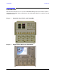
U3042AE12 Front and Rear Panel Features Front and Rear Panel Features Figure 3 Front Panel (Multiport Test Set) 1 of 12 Test Ports CPLR ARM SOURCE IN CPLR THRU Active LED Power Switch RCVR OUT Control Lines Voltage Adjust Ground Active LED • When the test set is connected and addressed by a PNA, the LED is On (illuminated). • The LED is Off (not illuminated) when the test set power switch is in Standby, or not addressed by a PNA.
U3042AE12 Front and Rear Panel Features Line Switch – Standby | – ON (Active LED On) Control Lines and Voltage Adjust For further information pertaining to control lines and voltage adjustments see “DUT Control Lines” on page 56. Figure 4 Rear Panel (Multiport Test Set) Bias Tee Input (Option 002) Line Module Test Set Interface Pass Through Interface Test Set Interface The Test Set Interface connector is used to send address and data to the test set from the PNA.
U3042AE12 Front and Rear Panel Features Available Fuses • Fuse (F 5 A/250V, 2110-0709) U.L. listed and CSA certified WARNING For continued protection against fire hazard replace line fuse only with same type and rating: • Fuse 5A/250V, Part Number 2110-0709 The use of other fuses or material is prohibited. Figure 5 Line Fuse CAUTION This instrument has autoranging line voltage input; be sure the supply voltage is within the specified range.
U3042AE12 System Setup with N5230A/C System Setup with N5230A/C WARNING The opening of covers or removal of parts is likely to expose dangerous voltages. Disconnect the instrument from all voltage sources while it is being opened. Preparing the N5230A/C Network Analyzer 1. Remove the feet from the bottom of the network analyzer. Refer to Figure 6. 2. Remove the 2 lower standoffs and screws (0515-1619) from the rear panel on the network analyzer. Figure 6 Rear Bottom Feet Standoffs (x2) Feet (x4) 3.
U3042AE12 System Setup with N5230A/C 4. Place the network analyzer on top of the Test Set and ensure that the front frame of the network analyzer is positioned slightly forward of the locks that are attached to the Test Set. Slide the network analyzer back so the locks engage the front frame of the analyzer. Refer to Figure 8.
U3042AE12 System Setup with N5230A/C N5230A/C RF Interface Cable Connections Figure 10 on page 16 illustrates the setup configuration of the U3042AE12 Multiport Test Set and how it should be configured to the PNA-L. 1. Connect the RF interconnect cables, supplied with this option, from the PNA-L to the Test Set. Torque each cable to 8 in-lb. Refer to Table 10 and Figure 10 on page 16. The Z5623-20418 are the short cables and the Z5623-20419 are the long cables.
U3042AE12 Controlling the Test Set with N5230A Controlling the Test Set with N5230A This section will describe how to setup and operate the U3042AE12 Multiport Test Set with the N5230A 4-Port PNA-L Network Analyzer. The U3042AE12 Multiport Test Set is considered a “slave” instrument. A PNA–L must be used to control the Test Set. There are three methods to control the Test Set. Multiport mode is recommended due to calibration and ease of use. • PNA Multiport Mode firmware revision ≥ A.07.50.
U3042AE12 Controlling the Test Set with N5230A Installing New Firmware Before installing new firmware into your PNA-L, you must store the mixer calibration files. 1. From the Start menu select run and enter 1 > OK. 2. Command line “Enter a Choice:”, using the front panel keys enter [6]. 3. Command line “Press any key to continue....”, use any front panel key.
U3042AE12 Controlling the Test Set with N5230A 4. Copy the following three mxcalfiles from D:\CALFILES to c:\Program Files\Agilent\Network Analyzer.
U3042AE12 Controlling the Test Set with N5230A N5230A Multiport Mode for Option 551 The PNA Multiport Mode selects the test set file that will enable the PNA to control the Test Set. The PNA Multiport Mode allows you to complete a N-Port calibration using the Cal Wizard application in the PNA. Refer to the PNA Help system for more information.
U3042AE12 Controlling the Test Set with N5230A How to Access Multiport Mode The Option 551 must be installed for Multiport capability. To access the multiport application select System > Configure > Multiport Capability. See Figure 12. Figure 12 System Configuration Select U3042AE12 (16-Port System) from the test set drop-down menu and select Restart as a Multiport PNA with this test set. Press OK.
U3042AE12 Controlling the Test Set with N5230A External Test Set Control Feature To verify that the network application has the U3042AE12 interface features, select Channel > External Test Set > Other. The U3042AE12 will be displayed as External Test Set Control-U3042AE12. See Figure 14. This menu will allow the physical Ports 1 thru 16 to be identified as any port for your convenience. For example; Port 5 can be named Port 2.
U3042AE12 Controlling the Test Set with N5230A Trace Measure S-Parameter S-Parameter selection can be accomplished using Trace Measure menu. Select TRACE > Measure. Use the drop-down menus to select 1 of 256 S-Parameters for the 16-Port system, see Figure 16. The first number in the Sxx selection is the Receiver Port and the second number will be the Source Port. Any port can be selected to be the Receiver, Source or both, as in S11.
U3042AE12 Figure 18 Controlling the Test Set with N5230A 16-Port New Trace Measure (S88 - S1212) Use the scroll bar to select.
U3042AE12 Controlling the Test Set with N5230A Balanced Tab: Balanced Measurements can be configured by selecting the Balance tab in the New Measurement menu. Refer to Figure 20. For more information on balanced (differential) component measurement, refer to the Application Note 1373-1 and 1373-2 (5988-5634EN and 5988-5635EN) at http://www.home.agilent.com. In the search menu type in “Multiport and Balanced.
U3042AE12 Controlling the Test Set with N5230A N-Port Calibration with N5230A It is recommended that you perform an ECal characterization to minimize the connections required for multiple port calibration. The N4691B Option M0F is recommended with cable (85131F) if you are calibrating at the PNA and test set ports. Characterize the ECal module with adapters that will not be used in the measurement of the DUT.
U3042AE12 Figure 23 Controlling the Test Set with N5230A 16-Port Calibration Help 3. Connect the ECal or the mechanical cal kit to the ports you are calibrating following the Cal Wizard prompts and press Measure after each connection. 4. At the Calibration Completed prompt, select Save As User Calset and type the name desired. Press Save. 5. After calibrating test set ports, use a quality load and short to verify the calibration on each port or end of the test cable.
U3042AE12 Controlling the Test Set with N5230A N5230A Interface Control The interface control will not function properly when using the mutliport mode. The multiport mode will reset the switch path commands of the interface control. It is recommended that the PNA be restarted in stand-alone mode if the interface control is being used. NOTE This section includes only the features required in the Interface Control for the U3042AE12 Multiport Test Set.
U3042AE12 Controlling the Test Set with N5230A How to Access Interface Control Settings with N5230A This section will describe how to setup and operate the U3042AE12 Multiport Test Set with the N5230A/C 4-Port Series Network Analyzer. To access the InterfaceControl application select Channel > InterfaceControl in the drop-down menu. NOTE The Agilent N5230A/C 4-Port PNA–L Series Network Analyzer comes with the Interface Control application.
U3042AE12 Controlling the Test Set with N5230A Test Set I/O Address and Data using Control Interface with N5230A An Instrument Preset will reset all of the fields to their default settings. NOTE If an error is encountered when sending Interface Control data, an error message is displayed on the PNA screen and the Channel Trigger State is set to Hold. You must fix the condition that caused the error, then change the Channel TriggeState to its original setting.
U3042AE12 Controlling the Test Set with N5230A Data: Positive integer is used to select switch position or state of DUT control interface line. Refer to Table 16 on page 62 through Table 23 on page 65. Address and data are separated by a period. Entries should be separated by a new line, or carriage return. For example: 0.0 16.1 32.2 The front-panel Enter key inserts a new line into the field. The number of Test Set I/O entries that can be entered is limited only by the available memory of the PNA.
U3042AE12 Controlling the Test Set with N5230A OK: Applies the settings and closes the dialog box. Cancel: Does not apply changes that were made and closes the dialog box. NOTE U3042AE12 Test Set I/O Commands can be found in Table 16 on page 62 through Table 23 on page 65. The Address and Data commands can be entered into the Test Set I/O control.
U3042AE12 Controlling the Test Set with N5230A How to Access GPIB Command Processor with N5230A 1. To access the GPIB Command Processor press: [Menu/Dialog] then tab to System, select Configure > SICL/GPIB 2.Select System Controller and GPIB Command Processor Console and select OK. NOTE User’s Guide If the PNA is not in System Controller mode, an error message appears and the GPIB Command Processor is disabled.
U3042AE12 Controlling the Test Set with N5230A GPIB Command Processor Console Write Commands Once the GPIB Command Processor Console is open, commands can remotely control the external Test Set I/O connector by sending the following: address: a integer number data: a integer number Address and data are separated by a comma. Commands should be separated by a new line, or carriage return.
U3042AE12 System Setup with N5242A System Setup with N5242A The opening of covers or removal of parts is likely to expose dangerous voltages. Disconnect the instrument from all voltage sources while it is being opened. WARNING Preparing the N5242A Network Analyzer 1. Remove the feet from the bottom of the network analyzer. Refer to Figure 24. 2. Remove the 2 lower standoffs and screws (0515-1619) from the rear panel on the network analyzer. Figure 24 Rear Bottom Feet Standoffs (x2) Feet (x4) 3.
U3042AE12 System Setup with N5242A 4. Install the two rear locking feet onto the U3042AE12. Looking at the front panel, the N5242-20138 is the right foot and the N5242-20139 is the left foot. Two screws (0515-2317) are included with this option. Refer to Figure 26. Figure 26 Install Locking Feet on U3042AE12 5. Place the network analyzer on top of the Test Set and ensure that the front frame of the network analyzer is positioned slightly forward of the locks that are attached to the Test Set.
U3042AE12 System Setup with N5242A 6. Secure the network analyzer’s lower locking feet to the Test Set upper locking feet, using the spring–loaded screws on the locking feet. Refer to Figure 28. If the network analyzer's lower locking feet are not aligned with the screw holes in the Test Set's upper locking feet, loosen the screws securing the feet to the instrument slightly to align. Figure 28 Locking Feet Screws NOTE There are two Lock-Feet kits available.
U3042AE12 System Setup with N5242A N5242A RF Interface Cable Connections Figure 29 on page 39 illustrates the setup configuration of the U3042AE12 Multiport Test Set and how it should be configured to the PNA-X. The cables have been supplied with Option 042. 1. Connect the RF interconnect cables from the PNA-X to the Test Set in the order listed. As you are connecting each cable, torque to 8 in-lb. The longer, straight end of each cable is connected to the test set.
U3042AE12 System Setup with N5242A Figure 29 indicates the final two digits of the part number for each cable. Figure 29 N5242A RF Interface Cable Connections 29 31 33 35 37 39 41 43 30 44 32 34 36 38 40 42 2. Connect the PNA-X Test Set I/O cable (8120-6818) to the U3042AE12 Test Set Interface on the rear panel.
U3042AE12 Controlling the Test Set with N5242A or N5230C Controlling the Test Set with N5242A or N5230C This section will describe how to setup and operate the U3042AE12 Multiport Test Set with the N5242A or N5230C. Both will be referred to as the PNA-X in this section. The U3042AE12 Multiport Test Set is considered a “slave” instrument. A PNA-X must be used to control the Test Set. There are three methods to control the Test Set. Multiport mode is recommended due to calibration and ease of use.
U3042AE12 Controlling the Test Set with N5242A or N5230C How to Access Multiport Mode The Option 551 must be installed for Multiport capability. To access the multiport application select Utility > System > Configure > Multiport Capability. See Figure 31. Figure 31 Selecting Multiport Mode Select U3042AE12 (16-Port System) from the test set drop-down menu and select Restart as a Multiport PNA with this test set. Press OK.
U3042AE12 Controlling the Test Set with N5242A or N5230C External Test Set Control Feature To verify that the network application has the U3042AE12 interface features, select Trace/Chan > Channel > Hardware Setup > External Test Set > Other. The U3042AE12 will be displayed as External Test Set Control-U3042AE12. See Figure 33, Figure 34 and Figure 35. Figure 33 External Test Set Control This menu will allow the physical Ports 1 thru 16 to be identified as any port for your convenience.
U3042AE12 Figure 34 Controlling the Test Set with N5242A or N5230C External Test Set U3042AE12 (Port 1 - 8) Select the Port Control down arrow for Ports 9 thru 16, see Figure 35.
U3042AE12 Controlling the Test Set with N5242A or N5230C Trace Measure S-Parameter S-Parameter selection can be accomplished using Response > Measure. Use the drop-down menus to select 1 of 256 S-Parameters for the 16-Port system, see Figure 36. The first number in the Sxx selection is the Receiver Port and the second number will be the Source Port. Any port can be selected to be the Receiver, Source or both, as in S11.
U3042AE12 Figure 38 Controlling the Test Set with N5242A or N5230C 16-Port New Trace Measure (S1 - S5) Use the scroll bar to select other s-parameter measurements Figure 39 User’s Guide 16-Port New Trace Measure (S1212 - S1616) 45
U3042AE12 Controlling the Test Set with N5242A or N5230C Balanced Tab: Balanced Measurements can be configured by selecting the Balance tab in the New Measurement menu. Refer to Figure 20 on page 25. For more information on balanced (differential) component measurement, refer to the Application Note 1373-1 and 1373-2 (5988-5634EN and 5988-5635EN) at http://www.home.agilent.com. In the search menu type in “Multiport and Balanced.
U3042AE12 Controlling the Test Set with N5242A or N5230C N-Port Calibration with N5242A or N5230C It is recommended that you perform an ECal characterization to minimize the connections required for multiple port calibration. The N4691B Option M0F is recommended with cable (85131F) if you are calibrating at the PNA and test set ports. Characterize the ECal module with adapters that will not be used in the measurement of the DUT.
U3042AE12 Controlling the Test Set with N5242A or N5230C 2. Continue following the Cal Wizard prompts. On the “Select Calibration Ports and ECal Module” window, press Select All or select the ports you are calibrating and press Next. Figure 43 16-Port Calibration Help 3. Connect the ECal or the mechanical cal kit to the ports you are calibrating following the Cal Wizard prompts and press Measure after each connection. 4.
U3042AE12 Controlling the Test Set with N5242A or N5230C N5242A or N5230C Interface Control The interface control will not function properly when using the mutliport mode. The multiport mode will reset the switch path commands of the interface control. It is recommended that the PNA be restarted in stand-alone mode if the interface control is being used. NOTE This section includes only the features required in the Interface Control for the U3042AE12 Multiport Test Set.
U3042AE12 Controlling the Test Set with N5242A or N5230C How to Access Interface Control Settings This section will describe how to setup and operate the U3042AE12 Multiport Test Set with the PNA-X. To access the Interface Control application select Trace/Chan > Channel > Hardware Setup > Interface Control in the drop-down menu. NOTE The PNA-X Series Network Analyzer comes with the Interface Control application. Please review this application before connecting the U3042AE12 Test Set to the PNA.
U3042AE12 Controlling the Test Set with N5242A or N5230C Test Set I/O Address and Data using Control Interface with N5242A or N5230C An Instrument Preset will reset all of the fields to their default settings. NOTE If an error is encountered when sending Interface Control data, an error message is displayed on the PNA screen and the Channel Trigger State is set to Hold. You must fix the condition that caused the error, then change the Channel TriggeState to its original setting.
U3042AE12 Controlling the Test Set with N5242A or N5230C Data: Positive integer is used to select switch position or state of DUT control interface line. Refer to Table 16 on page 62 through Table 23 on page 65. Address and data are separated by a period. Entries should be separated by a new line, or carriage return. For example: 0.0 16.1 32.2 The front-panel Enter key inserts a new line into the field.
U3042AE12 Controlling the Test Set with N5242A or N5230C OK: Applies the settings and closes the dialog box. Cancel: Does not apply changes that were made and closes the dialog box. NOTE U3042AE12 Test Set I/O Commands can be found in “Test Set I/O Interface Commands” on page 61. The Address and Data commands can be entered into the Test Set I/O control.
U3042AE12 Controlling the Test Set with N5242A or N5230C How to Access GPIB Command Processor 1. To access the GPIB Command Processor press: Utility > System > Configure > SICL/GPIB/SCPI. Figure 44 Utility Configure 2. Check System Controller and GPIB Command Processor Console and select OK.
U3042AE12 Controlling the Test Set with N5242A or N5230C GPIB Command Processor Console Write Commands Once the GPIB Command Processor Console is open, commands can remotely control the external Test Set I/O connector by sending the following: address: a integer number data: a integer number Address and data are separated by a comma. Commands should be separated by a new line, or carriage return.
U3042AE12 DUT Control Lines DUT Control Lines The 15 pin female D-Sub connector on the front panel provides 8 latched data connections that can be used to control your DUT. An adjustable voltage source (+2 to +5 Vdc) is provided on the front panel. A positive or negative external source can be used. Refer to Table 14 and Figure 49 on page 60. Setting the DUT Control Interface This section describes how to control the DUT control lines.
U3042AE12 DUT Control Lines NOTE All DUT control lines must be set with each command sent.
U3042AE12 DUT Control Lines Setting the Variable Source Voltage The output voltage of pin 12 can be varied from +2 to +5 V. Perform the following procedure to set the voltage: 1. Turn On U3042AE12. 2. Measure the voltage between pin 12 and 15 using a multimeter. 3. Rotate the voltage adjustment trimmer on the front panel until the multimeter indicates the appropriate voltage.
U3042AE12 DUT Control Lines Using an External Power Supply Figure 48 illustrates an example of the connection between the DUT and the U3042AE12 with an external dc power supply. Input the High and Low signals from the external power supply to the Positive Input and Negative Input respectively, and connect each line to the control terminal of the DUT. Turning On the U3042AE12 using an External Power Supply. 1. Turning On the U3042AE12. 2. Connect the DUT. 3. Turn On the external power supply.
U3042AE12 Table 14 DUT Control Lines DUT Control Specifications Item Specifications Connector Shape 15–pin female D–Sub Voltage Range: Figure 49 60 Positive Input 0 to +5 V Negative Input –5 to 0 V Maximum Current 100 mA (in total of each line) Impedance < 10 Ω Range of Variable Voltage +2 to +5 V Block Diagram of DUT Control User’s Guide
U3042AE12 Test Set I/O Interface Commands Test Set I/O Interface Commands Switch Address and Data Table 16 through Table 23 contain the information to set the internal switch paths of the U3042AE12 Test Set. Additional information regarding the operation and descriptions for the internal switches can be found in “Theory of Operation” on page 83. The address is the first value in the Test Set I/O control or GPIB data command. The second value controls the source and receiver paths of the ports.
U3042AE12 Test Set I/O Interface Commands Table 16 PNA Port 1 and Test Set Ports 1, 5, 9, 13 Address Decimal Data Description 0 D0 - D3 Controls SW100; Source to PNA Port 1 or Test Set Port 1, 5, 9 and 13. 0 D4 - D7 Controls SW101; Receiver to PNA Port 1 or Test Set Port 1, 5, 9 and 13.
U3042AE12 Table 18 Address Test Set I/O Interface Commands PNA Port 1 and Test Set Ports 6, 10 and 14 Decimal Data Description 16 D0 - D3 Controls SW200; Source to PNA Port 2 or Test Set Port 6, 10 and 14. 16 D4 - D7 Controls SW201; Receiver to PNA Port 2 or Test Set Port 6, 10 and 14.
U3042AE12 Test Set I/O Interface Commands Table 20 PNA Port 1 and Test Set Ports 7, 11 and 15 Address Decimal Data Description 32 D0 - D3 Controls SW300; Source to PNA Port 3 or Test Set Port 7, 11 and 15. 32 D4 - D7 Controls SW301; Receiver to PNA Port 3 or Test Set Port 7, 11 and 15.
U3042AE12 Test Set I/O Interface Commands Table 22 PNA Port 1 and Test Set Ports 8, 12 and 16 Address Decimal Data Description 64 D0 - D3 Controls SW400; Source to PNA Port 4 or Test Set Port 8 12 and 16. 64 D4 - D7 Controls SW401; Receiver to PNA Port 4 or Test Set Port 8 12 and 16.
U3042AE12 Operational Check Operational Check This operational check is to confirm the U3042AE12 and PNA operational performance. The operation verification limits provided ensure that your U3042AE12 and PNA are operating properly. Refer to “Troubleshooting Operational Check Failures” on page 80 to ensure the RF interface cables are installed and working correctly before returning the test set for repairs. Verification Limits Specifications for the U3042AE12 Multiport Test Set are typical.
U3042AE12 Operational Check Table 25 N5242A Operation Verification Limit for Reflection Tracking1 Standard2 Port 1-16 Options 001 or 002 Port 1-16 10 MHz to 4 GHz −10.0 dB 0 dB 4 GHz to 6 GHz −13.0 dB −2.5 dB 6 GHz to 10 GHz −16.0 dB −5.0 dB 10 GHz to 15 GHz −17.0 dB −7.5 dB 15 GHz to 20 GHz −25.0 dB −15.0 dB 20 GHz to 26.5 GHz −30.0 dB −40 dB Frequency 1. Reflection Tracking takes into account Source Loss, Receiver Loss, Margin, and PNA Mixer Cal. 2.
U3042AE12 Operational Check Operational Check Procedure The sequence of this procedure is very important and must be followed or the performance accuracy and results may vary from the reference plots provided. Ensure that the test set is not connected to the PNA if you are performing a PNA Operator’s Check. The PNA will indicate false failures if the test set is connected. Preparing the N5230A 1.
U3042AE12 Figure 50 Operational Check Test Set to N5230A Connections 12.Allow the ECal module, Test Set and PNA to warm up for a minimum of 30 minutes.
U3042AE12 Operational Check N5230A 1-Port Calibration and Verification Procedure 1. Connect the ECal or the mechanical cal kit to Port 1 or the port you are testing. Torque to 8 in-lb. For more information press the Help button, see Figure 51. Figure 51 ECal at N5230A Port 1 2. Perform a 1-Port Calibration on Port 1. On the PNA, press Calibration > Calibration Wizard. a. If using a mechanical cal kit, select SmartCal. b. If using an ECal module, select ECal. 3. Continue following the Cal Wizard prompts.
U3042AE12 Operational Check 5. At the Calibration Completed prompt, select Save As User Calset and type the name 999.1. Overwrite the Calset if it already exists. Press Save. NOTE Figure 53 If you do not have a key board, select Save As User Calset > Edit Name and save as 999.x. X is the port number you are calibrating. See Figure 53. Use the numeric keypad on the PNA front panel to enter "999.1." Calibration Complete 6. Repeat step 1 thru step 5 (1-Port Calibration Procedure) for Ports 2 thru 16.
U3042AE12 Operational Check 8. Select Calibration > Cal Set Viewer to launch the Cal Set Viewer toolbar. See Figure 54. Figure 54 Calibration, Cal Set Viewer 9. From the Cal Sets drop-down menu, select 999.1 and check Enable. Select the Reflection Tracking(1,1) term in the center drop-down menu and ensure that the Enable and Error Terms are selected as shown in Figure 55. You may also create a table on the PNA and enter the limit line stimulus and response values.
U3042AE12 Operational Check 10.Compare the Reflection Tracking (1,1) trace to the appropriate limits in Table 24 on page 66. This can be done using Limit Lines (press Trace > Limit Test) or Marker. The trace should be above the limit. PASS will be displayed on the screen if the limit lines are used. 11.Repeat step 9 and step 10 for Cal Sets “999.1” thru “999.16” (16-Port).
U3042AE12 Operational Check Preparing the N5242A or N5230C 1. Connect the Test Set to the N5242A 4-Port PNA-X using the interconnect cables as shown in Figure 29 on page 39 and Table 11 on page 38. If you are using a N5230C, refer to Figure 50 on page 69 and Table 10 on page 16. 2. Turn On the Test Set. 3. On the PNA, press Response > CAL > Manage CALS > CAL Set. Delete or Rename any Cal Sets titled “999.1” thru “999.16” (16-Port), although it is unlikely that you will find Cal Sets with these names. 4.
U3042AE12 Operational Check N5242A or N5230C 1-Port Calibration and Verification Procedure 1. Connect the ECal or the mechanical cal kit to Port 1 or the port you are testing. Refer to Figure 2 on page 2. Torque to 8 in-lb. For more information press the Help button, see Figure 59. 2. Perform a 1-Port Calibration on Port 1. On the PNA, press Response > CAL > Start Cal > Calibration Wizard. a. If using a mechanical cal kit, select SmartCal. b. If using an ECal module, select ECal. 3.
U3042AE12 Figure 60 Operational Check Calibration Complete 6. Repeat step 1 thru step 5 (1-Port Calibration Procedure) for Ports 2 thru 16. When finished, there should be sixteen Cal Sets saved with the titles “999.1” thru “999.16” (16-Port). If you are using an ECal module you can verify the individual port calibration by selecting Response > CAL > More > ECAL > ECAL Confidence Check. For further information refer to the system Help menu. 7. Press Trace/Chan > Trace > Delete Trace.
U3042AE12 Operational Check 8. To launch the Cal Set Viewer toolbar. Select Response > CAL > Manage CALS > CAL Set Viewer. Figure 61 Calibration, Cal Set Viewer 9. From the Cal Sets drop-down menu, select 999.1 and check Enable. Select the Reflection Tracking(1,1) term in the center drop-down menu and ensure that the Enable and Error Terms are selected. NOTE Figure 62 User’s Guide You may also create a table on the PNA and enter the limit line stimulus and response values.
U3042AE12 Operational Check Figure 63 Option 001 or 002 Reflection Tracking Trace (Port 1-4) with N5242A 10.Compare the Reflection Tracking (1,1) trace to the appropriate limits in Table 24 on page 66. This can be done using Limit Lines (press Marker/Analysis > Analysis > Limit Test). The trace should be above the limit. PASS will be displayed on the screen if the limit lines are used. If you are using an N5230C, refer to Figure 55 on page 72, Figure 56 and Figure 57 on page 73. 11.
U3042AE12 Operational Check Figure 65 Standard Reflection Tracking Trace (Port 1-4) with N5242A Figure 66 Standard Reflection Tracking Trace (Port 5-16) with N5242A NOTE Response from 10 MHz to 500 MHz is normal due to the PNA-X couplers in comparison to the U3042AE12 bridges. The bridges have more gain in the coupled RF path.
U3042AE12 Troubleshooting Operational Check Failures Troubleshooting Operational Check Failures If your test results fail the Operational Check limits, verify following: 1. Insure that the test set is turned on and connected properly to the PNA. 2. Check all appropriate network analyzer and test set connectors for damage, cleanliness, and proper torque. 3. Repeat the relevant 1-Port calibrations. 4.
U3042AE12 Service Information Service Information Refer to “Contacting Agilent” on page 94. WARNING No operator serviceable parts inside. Refer servicing to qualified personnel. To prevent electrical shock do not remove covers. WARNING These servicing instructions are for use by qualified personnel only. To avoid electrical shock, do not perform any servicing unless you are qualified to do so.
U3042AE12 Description Service Information Agilent Part Number PNA-L or PNA-X Locking Feet 5023-0132 PNA-L Test Set Locking Feet 5063-9253 User’s Guide (Option E12) 82 U3042-90001 User’s Guide
U3042AE12 Theory of Operation Theory of Operation The following is a description of the operation of the U3042AE12. Reference the U3042AE12 block diagrams shown in Figure 67 on page 85. This section assumes the user has a general understanding of couplers, switches, and network analyzers. RF Switch Components There are eight quad switches. The switches select the RF paths from the PNA source and receiver through interconnect cables to test set port paths 5 thru 16.
U3042AE12 Theory of Operation S301 - Receiver to Ports (3, 7, 11 and 15) Switch 301 provides control of the A Receiver path to PNA Port 3 and ports 7, 11 and 15 to the Test Set. In the state shown in the block diagram, switch 301 routes the Coupler Arm from the PNA Port 3 to the A Receiver and all unused Test Set ports (7, 11 and 15) Coupler Arm paths are terminated.
User’s Guide Port 9 Port 5 SW 100 1 2 3 4 3 SW 101 2 4 C 1 Port 14 Port 10 Port 6 SW 200 SW 201 Module 2 Port 11 Port 7 SW 301 RCVR D OUT SOURCE SOURCE RCVR C OUT SOURCE RCVR A OUT PNA P3 JUMPERS Port 16 Port 12 Port 8 SW 400 SW 401 Module 4 PNA P4 JUMPERS SOURCE PNA P2 JUMPERS Port 15 SW 300 Module 3 RCVR B OUT PNA P1 JUMPERS C Module 1 Figure 67 Port 13 U3042AE12 Standard U3042AE12 Theory of Operation System Block Diagram U3042AE12 Standard Configuration CPLR
86 Port 13 Port 9 Port 5 1 2 3 4 3 SW 101 2 4 C 1 Port 14 Port 10 Port 6 SW 200 SW 201 Module 2 Port 11 Port 7 SW 301 RCVR D OUT SOURCE RCVR C OUT SOURCE RCVR A OUT SOURCE PNA P3 JUMPERS Port 16 Port 12 Port 8 SW 400 SW 401 Module 4 PNA P4 JUMPERS SOURCE PNA P2 JUMPERS Port 15 SW 300 Module 3 RCVR B OUT PNA P1 JUMPERS C Module 1 Figure 68 SW 100 U3042AE12 Option 001 Note: All amplifiers have attenuators on outputs, not shown in block diagram.
User’s Guide Port 13 Port 9 Port 5 1 2 3 4 3 C 4 C 1 Port 14 Port 10 Port 6 SW 200 SW 201 Module 2 Port 11 Port 7 SW 301 SOURCE RCVR C OUT SOURCE RCVR A OUT PNA P3 JUMPERS RCVR D OUT PNA P2 JUMPERS Port 15 SW 300 Module 3 Port 16 Port 12 Port 8 SW 400 PNA P4 JUMPERS SW 401 Module 4 RCVR B OUT PNA P1 JUMPERS SW 101 2 Module 1 Figure 69 SW 100 U3042AE12 option 002 Note: All amplifiers have attenuators on outputs, not shown in block diagram.
U3042AE12 Safety and Regulatory Information Safety and Regulatory Information Introduction Review this product and related documentation to familiarize yourself with safety markings and instructions before you operate the instrument. The documentation contains information and warnings that must be followed by the user to ensure safe operation and to maintain the product in a safe condition. Before Applying Power Verify that the premises electrical supply is within the range of the instrument.
U3042AE12 Safety and Regulatory Information Compliance with German Noise Requirements This is to declare that this instrument is in conformance with the German Regulation on Noise Declaration for Machines (Laermangabe nach der Maschinenlaermrerordnung-3. GSGV Deutschland). Acoustic Noise Emission/Geraeuschemission LpA<70 dB Lpa<70 dB Operator Position am Arbeitsplatz Normal Operation normaler Betrieb per ISO 7779 nach DIN 45635 t.
U3042AE12 Safety and Regulatory Information Warnings WARNING The WARNING notice denotes a hazard. It calls attention to a procedure, practice, or the like, which if not correctly performed or adhered to, could result in personal injury. Do not proceed beyond a WARNING notice until the indicated conditions are fully understood and met.
U3042AE12 Safety and Regulatory Information Cautions CAUTION The CAUTION notice denotes a hazard. It calls attention to an operating procedure, practice, or the like, which if not correctly performed or adhered to, could result in damage to the product or loss of important data. Do not proceed beyond a CAUTION notice until the indicated conditions are fully understood and met. Cautions applicable to this instrument are: CAUTION Always use the three-prong ac power cord supplied with this instrument.
U3042AE12 Safety and Regulatory Information Instrument Markings The instruction documentation symbol. The product is marked with this symbol when it is necessary for the user to refer to the instructions in the documentation. This symbol indicates that the instrument requires alternating current (ac) input. This symbol indicates separate collection for electrical and electronic equipment, mandated under EU law as of August 13, 2005.
U3042AE12 Electrostatic Discharge Protection Electrostatic Discharge Protection Protection against electrostatic discharge (ESD) is essential while removing assemblies from or connecting cables to the network analyzer. Static electricity can build up on your body and can easily damage sensitive internal circuit elements when discharged. Static discharges too small to be felt can cause permanent damage.
U3042AE12 Contacting Agilent Contacting Agilent Assistance with test and measurement needs, and information on finding a local Agilent office are available on the Internet at: http://www.agilent.com/find/assist You can also purchase accessories or documentation items on the Internet at: http://www.agilent.com/find If you do not have access to the Internet, contact your field engineer.