User guide
Manuals
Brands
Agilent Technologies Manuals
Business equipment
N4962A
79
80
81
82
83
84
85
86
87
88
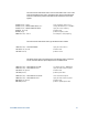
Table Of Contents
1 Getting Started
1.1 General
1.1.1 Key Features
1.1.2 Internal clock system
1.1.3
1.1.3 PRBS generator
1.1.4 Error detector
1.1.5 Operating modes
1.1.6 Display
1.1.7 Data entry / interface
1.2 N4962A Operation Overview
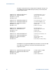
1.3 Getting Started with the N4962A Serial BERT 12.5 Gb/s
1.3.1 Unpacking and Installation
1.3.2
1.3.2 Safety and Regulatory
1.3.3 Declaration of Conformity
1.3.4 Important Notes
1.3.5 Performance Recommendations
1.4 Connect the Hardware
1.5 Turn It On
1.6
1.6 Align Clock and Data
1.7 Make the Measurement
2 N4962A System Overview
2.1 Front Panel Quick Reference
2.2 Rear Panel Quick Reference
2.3 Connector Care
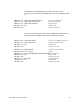
3 System Details and Performance Specifications
3.1 General
3.2 Safety and Regulatory
3.3 Internal Clock
3.4 PRBS Generator
3.5 Error Detector
3.6
3.6 Data Path
4 Operation
4.1 General Information
4.1.1 Performance Recommendations
4.1.2 Connector Care
4.2 Front Panel Interface
4.2.1
4.2.2 Front Panel – Display Panel
4.2.3 Front Panel – Local, Receiver, and Data Path Controls
4.2.4
4.2.3 Front Panel – Configuration Adjustment Controls
4.2.4
4.2.5 Front Panel – Display Selection Controls
4.3 Rear Panel Interface
4.4 Power-On State
4.5 System Verification
4.5.1 Self Test Mode
4.5.2 Error Free Test
4.5.3 High BER Test
4.5.4 Low BER Test
4.6 BER Detector Clock Phase Adjustment
4.7 Basic BER Measurement
5 Remote GPIB Interface
5.1 GPIB Capabilities
5.2 GPIB Command Syntax
5.2.1 Command Structure
5.3 IEEE Common Commands
5.4 SCPI Mandated Commands
5.5 N4962A Device Commands
5.5.1 Internal Clock Commands
5.5.2 PRBS Pattern Commands
5.5.3 Measurement Commands
5.6 Examples
6 Returning the N4962A Serial BERT to Agilent Technologies
1
...
...
85
86
87
88