
User guide
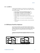
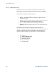
Table Of Contents
- 1 Getting Started
- 2 N4962A System Overview
- 3 System Details and Performance Specifications
- 4 Operation
- 5 Remote GPIB Interface
- 6 Returning the N4962A Serial BERT to Agilent Technologies
Operation
52
Serial BERT 12.5 Gb/s User Guide
If the sampling point occurs near the PRBS transition point, the sampled value
is uncertain and many bit errors will be measured by the detector. Adjusting
the phase away from the transition point will optimally position the sampling
point and allow the best chance of measuring error-free operation.
The N4962A can automatically detect and set the detector clock phase for the
best sampling point. It requires that the system settings and data path allow
error-free operation. This is best achieved by putting the system into self-test
mode, described in Section 4.5.1.
If the configuration settings result in high errors (eg: PRBS output amplitude
set low), or the cabling or DUT result in poor eye quality, the automatic
detector clock phase adjustment will not work. It will also be difficult to set the
clock phase adjustment manually.
To automatically set the detector clock phase adjustment:
With the N4962A powered, clocks connected, and data path connected:
• Ensure the Data Path > Enabled option is selected (PRBS output must
be on)
• Ensure the Receiver > On is not selected (the error detector must be
off)
• Press the Display > Scroll ↓ button and select Ø
• Press the Adjust > Config State + button to auto-select the detector
phase
• Observe the Error ε light (should remain off, indicating no errors
detected)
To manually set the detector clock phase adjustment:
With the N4962A powered, clocks connected, and data path connected:
• Ensure the Data Path > Enabled option is selected (PRBS output must
be on)
• Ensure the Receiver > On is not selected (the error detector must be
off)
• Press the Display > Scroll ↓ button and select Ø
Find the optimal sampling point as follows:
• If the Error ε light is off, press the Adjust > Ø + button until the light is
on
• Press the Adjust > Ø + button until the Error ε light remains off
• Record the clock phase adjustment value
• Press the Adjust > Ø + button until the Error ε light remains on