
User guide
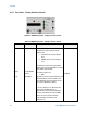
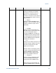
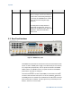
Table Of Contents
- 1 Getting Started
- 2 N4962A System Overview
- 3 System Details and Performance Specifications
- 4 Operation
- 5 Remote GPIB Interface
- 6 Returning the N4962A Serial BERT to Agilent Technologies
Operation
46
Serial BERT 12.5 Gb/s User Guide
Text
Type
Description
Default
will remain on the Config State display
item. For example, the first state shown is
the PAT 2Exx, and the Config State light is
lit. Pressing Scroll DOWN selects the MS
0.xxx state, and the Config State light
remains lit.
The Config State currently selected is
indicated
by the display text. There is no
indicator for the different states. States are
described in
Table 13, and detailed in
Section
4.2.3.
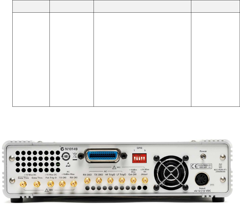
4.3 Rear Panel Interface
Figure 13. N4962A rear panel
The N4962A rear panel features connectors for the internal and external clock
system, as well as a PRBS pattern trigger, and a differential pair of connectors
for a unique data path (DataThru). The rear panel also includes a 5-bit GPIB
address switch, and a GPIB connector. The panel also features the N4962A
power switch, and a built-in cooling fan.
The DataThru/DataThru¯¯¯¯¯¯ connectors (both SMA) are connected to the IN/IN¯¯
connectors when the Data Path option is set to Thru (detailed in Section 2.5).
The PRBS generator is enabled and is available from the OUT/OUT¯¯¯ connectors
when this data path is selected. The input signal is not processed by the error
detector, and errors are not counted.