
User guide
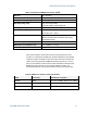
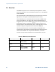
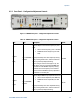
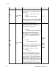
Table Of Contents
- 1 Getting Started
- 2 N4962A System Overview
- 3 System Details and Performance Specifications
- 4 Operation
- 5 Remote GPIB Interface
- 6 Returning the N4962A Serial BERT to Agilent Technologies

System Details and Performance Specifications
Serial BERT 12.5 Gb/s User Guide 31
Table 8. Parameters for N4962A error detector (IN, IN¯¯)
Data rate 0.5 to 12.5 Gb/s
PRBS patterns 2
n
– 1, n=7, 10, 15, 23, 31
Data input sensitivity (single ended) 0.1 V pp typical
Data input voltage range 2 Vpp max (single-ended)
± 0.5 V DC common mode voltage max
Data input phase adjust 0 to 360°
Data input phase adjust resolution 2° for data rates ≥ 5 Gb/s
90° for data rates < 5 Gb/s
Data input external interface
Differential. DC coupled, 50 Ω nominal, female SMA
(May be operated single end without unused input
terminated into 50 Ω)
RXCKI Clock input frequency range 0.5 to 12.5 GHz
RXCKI Clock input amplitude range +4 to +10 dBm (1 to 2 V pp)
RXCKI Clock input external interface AC coupled, 50 Ω nominal, female SMA
After the error detector synchronizes with the incoming bit stream, and is
turned on, it compares the sampled input bit stream against the synchronized
comparison signal. The detector counts the number of bit errors and the total
number of bits, and generates the BER measurement (# bit errors / total #
bits). The error detector counter sizes have been selected to enable long-term
BER measurements without counter overflow, detailed in Table 9. The
measurement will stop if one of these counters reaches the maximum value.
Table 9. N4962A error detector counter specifications
Counter
Counter Size
Overflow Time at 1
2.5 Gb/s
Bit
errors
48 bits
~12.5
hours (0.5 BER), 2606 days (1E-4 BER)
Total bits
56 bits
1601 hours (67
days)
Elapsed time bits
22 bits
4194304 seconds (48.5 days)