
User guide
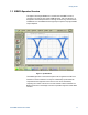

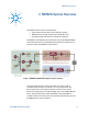
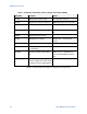
Table Of Contents
- 1 Getting Started
- 2 N4962A System Overview
- 3 System Details and Performance Specifications
- 4 Operation
- 5 Remote GPIB Interface
- 6 Returning the N4962A Serial BERT to Agilent Technologies
N4962A System Overview
Serial BERT 12.5 Gb/s User Guide 19
Controls
Local (button & light)
–
indicates local (vs. remote) control; button selects local
control
Receiver
>
On (button & light)
– indicates detector state; button toggles & resets BER
Data Pa
th >
PRBS
¯¯¯¯ (button & light) – indicates inversion of PRBS signal; button toggles
Select Path (button & 3 lights)
– data path (disabled, enabled, thru); button
cycles
Adjust
>
Freq (2 buttons)
– adjust the internal clock frequency up or down (shown on
display)
Ampl (2 buttons)
– adjust the PRBS output amplitude up or down (shown on
display)
ø (2 buttons)
– adjust the detector clock phase up or down (shown on display)
Config State (2 buttons)
– change value of the currently-displayed
configuration state
.
Display
>
Scroll (2 buttons & 6 lights)
– select which feature is shown on the display
panel:
• BER – measured BER (# bit errors / total # bits)
• ε time (sec) – elapsed time of BER measurement, in seconds
• Ampl (V) – single-ended PRBS gen
erator output amplitude, in volts per
side
• Freq (GHz) – internal clock frequency, in GHz (10 GHz corresponds to
10 Gb/s)
• Ø – BER clock phase adjustment, in degrees (360-degrees = 1 UI)
• Config State– selects one of the configuration states shown in Table 1.