
User guide
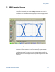

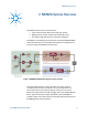
Table Of Contents
- 1 Getting Started
- 2 N4962A System Overview
- 3 System Details and Performance Specifications
- 4 Operation
- 5 Remote GPIB Interface
- 6 Returning the N4962A Serial BERT to Agilent Technologies
N4962A System Overview
Serial BERT 12.5 Gb/s User Guide 17
2 N4962A System Overview
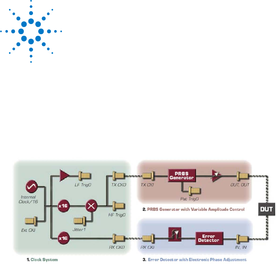
The N4962A consists of three functional blocks:
• Internal/external clock system with analog jitter injection
• PRBS generator (TX) with variable output amplitude control
• Error detector (RX) with electronic clock phase adjustment
The N4962A is controlled by front-panel buttons and remote GPIB (IEEE 488.2)
commands; information is conveyed with LED indicators and a display on the
front panel, along with GPIB data communication.
Figure 2. N4962A simplified block diagram; system overview
The clock system features an internal generator that creates a 9.85 to
11.35 GHz system clock from an internal 1/16
th
-rate clock generator. The
internal clock/16 can also be phase locked to an external 1/16
th
clock if
desired. The high-frequency TX clock and trigger output can be FM-modulated
with an optional external jitter signal. Alternatively, external 500 Mb/s to
12.5 Gb/s clocks can be used in place of the internal high-frequency clocks for
the PRBS generator and error detector.