medium_standard.
medium_standard.book Page 2 Friday, September 10, 2010 2:45 PM Notices © Agilent Technologies, Inc. 2010 Warranty No part of this manual may be reproduced in any form or by any means (including electronic storage and retrieval or translation into a foreign language) without prior agreement and written consent from Agilent Technologies, Inc. as governed by United States and international copyright laws.
medium_standard.
medium_standard.
medium_standard.
medium_standard.book Page 6 Friday, September 10, 2010 2:45 PM Inspecting the probe • Inspect the shipping container for damage. Keep a damaged shipping container or cushioning material until the contents of the shipment have been checked for completeness and the instrument has been checked mechanically and electrically. • Check the accessories. Accessories supplied with the probe are listed in “Accessories Supplied” in Table 1.
medium_standard.book Page 7 Friday, September 10, 2010 2:45 PM Accessories Supplied The following is a list of supplied accessories.
medium_standard.book Page 8 Friday, September 10, 2010 2:45 PM Notes on Safety This device is designed to comply with IEC 61010 Safety Standards, and has been thoroughly tested for safety prior to shipment. However, mishandling during use could result in injury or death, as well as damage to the device. Be certain that you understand the instructions and precautions in the manual before use. We disclaim any responsibility for accidents or injuries not resulting directly from device defects.
medium_standard.book Page 9 Friday, September 10, 2010 2:45 PM Notes on Use WARNIN G To avoid short circuits and potentially life- threatening hazards, follow these precautions. • Never attach the clamp to a circuit that operates at more than the maximum rated voltage to earth. • For safety's sake, avoid clamping around bare conductors, while clamping or measuring. • While clamping and measuring, do not touch the clamp in front of the barrier or the conductor being measured.
medium_standard.book Page 10 Friday, September 10, 2010 2:45 PM WARNIN G • If the waveform measuring instrument being connected to the output terminal (BNC) on this device is equipped with any other measurement terminals, take the following precautions to ensure that the other instrument does not form a bridge between the probe and any hazardous live part of a part.
medium_standard.book Page 11 Friday, September 10, 2010 2:45 PM CAUTION • To avoid damage to the device, protect it from vibration or shock during transport and handling, and be especially careful to avoid dropping. • Do not store or use the device where it could be exposed to direct sunlight, high temperature, humidity, or condensation. Under such conditions, the device may be damaged and insulation may deteriorate so that it no longer meets specifications.
medium_standard.book Page 12 Friday, September 10, 2010 2:45 PM CAUTION 12 • Do not place any unclamped conductor with an electric current of a frequency of 10 kHz or more near the sensor head. Current flowing in the conductor nearby may heat up the sensor head and cause its temperature to rise, leading to damage to the sensor.
medium_standard.book Page 13 Friday, September 10, 2010 2:45 PM Cleaning the Probe If the probe requires cleaning, disconnect it from the oscilloscope and clean it with a soft cloth dampened with a mild soap and water solution. Make sure the probe is completely dry before reconnecting it to the oscilloscope.
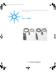
medium_standard.book Page 14 Friday, September 10, 2010 2:45 PM Description of Probe Parts for the N2780A/B and N2781A/B Terminator “LOCK/UNLOCK” indication Current direction indication 6 8 3 2 9 Sensor 1 4 (inside) Power supply cable 10 7 Sensor cable 1 Clamp This clamps around the conductor to be measured. 2 Slider This slider opens the clamp. Always use it to open and close the clamp 3 Lever This lock mechanism keeps the clamp closed.
medium_standard.book Page 15 Friday, September 10, 2010 2:45 PM 5 Barrier This structure reduces the likelihood of touching the conductor while testing, and indicates the limit of safe physical contact. Avoid touching the clamp in front of the barrier when clamping or measuring. 6 Demagnetizing switch (DEMAG) This demagnetizes the core if it has been magnetized by switching the power on and off, or by an excessive input. Always carry out demagnetizing before a measurement.
medium_standard.book Page 16 Friday, September 10, 2010 2:45 PM Description of Probe Parts for the N2782A/B and N2783A/B Current direction Sensor Terminator 3 “LOCK/UNLOCK” indication 1 6 7 2 8 Power supply cable Sensor cable 4 5 1 Opening lever Operating lever for opening the sensor head. Always use this lever to open the sensor head. 2 Sensor head This clamps the conductor being measured, and carries out the actual current measurement.
medium_standard.book Page 17 Friday, September 10, 2010 2:45 PM This demagnetizes the core if it has been magnetized by switching the power on and off, or by an excessive input. Always carry out demagnetizing before measurement. The demagnetizing process takes about one second. During demagnetizing, a demagnetizing waveform is output. 4 Zero adjustment dial (ZERO ADJ) Use the zero adjustment dial to correct for the effect of a voltage offset or temperature drift on the unit.
medium_standard.book Page 18 Friday, September 10, 2010 2:45 PM Specifications and Characteristics The following specifications are guaranteed. Specifications (Warranted) N2780A/B N2781A/B Amplitude ±1.0% of reading ±500 mA ±1.0% of reading ±100 mA at 23 oC ± 3 o accuracy at 23 oC ± 3 oC (DC or 45 to 66 Hz, up to maximum continous current) 18 N2782A/B ±1.0% of reading ±10 mA at 23 oC ± 3 oC N2783A/B ±1.
medium_standard.book Page 19 Friday, September 10, 2010 2:45 PM Characteristics (Non-warranted) N2781A/B DC to 10 MHz (-3 dB) (Typical characteristic shown in Figure 6) Rise time 175 ns or less 35 ns or less Maximum current 500 A rms (Derating 150 A rms (Derating according to ! (continuous) rms according to frequency shown in frequency shown in Figure 2) Figure 7) Maximum peak 700 A peak 300 A peak 500 A peak; at pulse ! current value (non-continuous) width £ 30 ms Output voltage rate 0.01 V/A (100:1) 0.
medium_standard.book Page 20 Friday, September 10, 2010 2:45 PM General Characteristics Diameter of measurable conductors Cable lengths (Approximately) Sensor Power supply External dimensions Sensor (Approximately) Terminator Weight (Approximately) N2780A/B 20 mm (0.79”) N2781A/B 20 mm (0.79”) N2782A/B 5 mm (0.2”) N2783A/B 5 mm (0.2”) 2 m (78.7”) 1 m (39.4”) W H D 176 69 27 mm 6.93” 2.72” 1.06” 27 55 18 mm 1.06” 2.17” 0.71” 520 g (18.3 oz.) 2 m (78.7”) 1 m (39.4”) W H D 176 69 27 mm 6.93” 2.72” 1.
medium_standard.
medium_standard.book Page 22 Friday, September 10, 2010 2:45 PM Insertion Impedance N2780A/B Insertion impedance [] Figure 3 Frequency [Hz] Deviation [%] Figure 4 DC Accuracy Characteristic N2780A/B 5 4 3 2 1 0 -1 -2 -3 -4 -5 upper limit lower limit N2780A 0.
medium_standard.book Page 23 Friday, September 10, 2010 2:45 PM Deviation [%] Figure 5 AC Amplitude Accuracy Characteristic N2780A/B 5 4 3 2 1 0 -1 -2 -3 -4 -5 upper limit lower limit N2780A 0.
medium_standard.
medium_standard.book Page 25 Friday, September 10, 2010 2:45 PM Figure 9 DC Accuracy Characteristic N2781A/B 25 Deviation [%] 20 15 upper limit lower limit 10 N2781A 5 0 -5 0.1 1 10 100 1000 DC Current [A] Figure 10 AC Amplitude Accuracy Characteristic N2781A/B 25 Deviation [%] 20 15 upper limit 10 lower limit N2781A 5 0 -5 0.
medium_standard.
medium_standard.book Page 27 Friday, September 10, 2010 2:45 PM Insertion impedance [] Figure 13 Insertion Impedance N2782A/B Frequency [Hz] Figure 14 DC Accuracy Characteristic N2782A/B 25 Deviation [%] 20 15 upper limit 10 lower limit N2782A 5 0 -5 0.001 0.01 0.
medium_standard.book Page 28 Friday, September 10, 2010 2:45 PM Figure 15 AC Amplitude Accuracy Characteristic N2782A/B 25 Deviation [%] 20 15 upper limit lower limit 10 N2782A 5 0 -5 0.001 0.01 0.
medium_standard.
medium_standard.book Page 30 Friday, September 10, 2010 2:45 PM Figure 19 DC Accuracy Characteristic N2783A/B 20 15 Deviation [%] 10 5 upper limit 0 lower limit N2783A -5 -10 -15 -20 0.001 0.01 0.1 1 10 100 DC Current [A] Figure 20 AC Amplitude Accuracy Characteristic N2783A/B 12 Deviation [%] 9 6 upper limit 3 lower limit N2783A 0 -3 -6 0.001 0.01 0.
medium_standard.book Page 31 Friday, September 10, 2010 2:45 PM Measurement Procedure Preparations for Measurement CAUTION 1 Have the N2779A power supply and oscilloscope ready for waveform measurement ready. Before turning on the power, make sure that the voltage of the power supply being used matches the supply voltage indicated on the rear panel of the N2779A. 2 Turn the power switch off and connect the power cord. 3 Connect the power plug of the current probe to the power receptacle of the N2779A.
medium_standard.book Page 32 Friday, September 10, 2010 2:45 PM 3 Connect the output connector of the current probe to the input connector of the oscilloscope. Turn the collar until it clicks, and check that it is locked securely. CAUTION • When disconnecting the output connector, be sure to release the lock, then pull the connector. Forcibly pulling the connector without releasing the lock, or pulling on the cable will result in damage to the terminator.
medium_standard.book Page 33 Friday, September 10, 2010 2:45 PM Making the Measurement 1 Check that the system is safe and that the preparations described in the preceding section have been carried out. 2 Pull the sensor opening lever with the sensor head opens. 3 Align the sensor so that the current direction indication corresponds to the direction of current flow through the conductor to be measured. Also, align the clamp so that the conductor is in the center of the sensor aperture.
medium_standard.book Page 34 Friday, September 10, 2010 2:45 PM CAUTION • The maximum continuous input range is based on heat that is internally generated during measurement. Never input current in excess of this level. Exceeding the rated level may result in damage to the probe. • The maximum continuous input range varies according to the frequency of the current being measured.
medium_standard.book Page 35 Friday, September 10, 2010 2:45 PM CAUTION • When opening the sensor head of the probe, be sure to operate with the opening lever. If an upper core is forced to open when the sensor head is locked, the open- close mechanism can be damaged.
medium_standard.book Page 36 Friday, September 10, 2010 2:45 PM N O TE • The output of this unit is terminated internally. Use an oscilloscope with an input impedance of at least 1 M or use the Agilent E2697A impedance adapter. • Immediately after powering on the probe, the probe may be subject to an appreciable offset drift due to the effect of self- heating. To counteract this, allow the probe to warm up for about 30 minutes before carrying out measurement.
medium_standard.book Page 37 Friday, September 10, 2010 2:45 PM N O TE • At high frequencies, common mode noise may affect measurements taken on the high voltage side of circuits. If this occurs, reduce the frequency range of the waveform measuring instrument or clamp onto the low- voltage side of the circuit, as appropriate.
medium_standard.
medium_standard.
medium_standard.book Page 40 Friday, September 10, 2010 2:45 PM Service Strategy To return the probe to optimum performance requires factory repair. If the probe is under warranty, normal warranty services apply. To return the current probe to Agilent Technologies for Service In the U.S., call (800) 829- 4444 for further details and the location of your nearest Agilent Technologies service center. Outside the U.S.
medium_standard.book Page 41 Friday, September 10, 2010 2:45 PM Performance Verification Testing Required Test Equipment Description Probe Power Supply Digital Multimeter (DMM) Signal Generator Adapter Test Coil Critical Specifications Recommended No substitute Agilent N2779A AC/DC voltage and current measurement Agilent 34401A accuracy better than ±0.
medium_standard.book Page 42 Friday, September 10, 2010 2:45 PM Test Coil Construction for the N2782A/B and N2783A/B Construct a 5- turn coil with a diameter of about 4 inches (10 cm) using transformer wire. 5 turns Amplitude Accuracy Test The following procedure measures the accuracy of the current probe. 1 Connect the equipment as shown below.
medium_standard.book Page 43 Friday, September 10, 2010 2:45 PM test procedure. While the test system is warming up, clean the magnetic contacts on the probe jaw. DMM Adapter Probe Power Supply Signal Generator ! SENSE 01 01 COM COM Current Probe Test Coil 2 Press the DEMAG button on the probe terminator. 3 Configure the DMM to measure AC Volts. 4 Clamp the probe around the coil and ensure that the probe is as perpendicular as possible to the coils of wire.
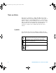
medium_standard.book Page 44 Friday, September 10, 2010 2:45 PM • Amplitude: N2780A/B 6.5 A rms N2781A/B 3 A rms N2782A/B 6 A rms N2783A/B 6 A rms • Offset: 0.0 Vdc 6 Measure the voltage output of the probe on the DMM and record this value in Table 2. 7 Do the current calculation by multiplying the DMM Voltage by the value in the Multiplier column of Table 2 and record the answer in the Calculated Amperes column for the probe you are measuring.
medium_standard.
medium_standard.book Page 46 Friday, September 10, 2010 2:45 PM www.agilent.com Agilent Technologies, Inc.