Agilent N1022A Active Probe Adapter User Guide
Notices © Agilent Technologies, Inc. 2003 Warranty Safety Notices No part of this manual may be reproduced in any form or by any means (including electronic storage and retrieval or translation into a foreign language) without prior agreement and written consent from Agilent Technologies, Inc. as governed by United States and international copyright lays. The material contained in this document is provided “as is,” and is subject to being changed, without notice, in future editions.
Contents N1022A Active Probe Adapter 1 General Safety Considerations 2 Instrument Markings 3 Using the Probe Adapter 4 Inspecting the N1022A 4 Connecting the N1022A 5 Static-Safe Workstation 8 Reducing ESD Damage 9 Specifications and Regulatory Information 10 Specifications 10 Regulatory Information 13 Declaration of Conformity 14 Service 15 Checking Probe Power Outputs 15 Returning the N1022A 16 Agilent Technologies Service Offices 17 Contents 1
Contents Contents 2
N1022A Active Probe Adapter N1022A Active Probe Adapter The N1022A Active Probe Adapter provides the interface to connect an Agilent Infiniimax Active Probe to an Agilent 86100-series Infiniium DCA. To use the N1022A requires that firmware revision A.03.05 or later be installed on the Infiniium DCA. The Infiniimax Active Probes include the following: 1131A, 1132A, and 1134A. Other supported active probes include the 1152A, 1156A, 1157A, and 1158A.
General Safety Considerations General Safety Considerations This product has been designed and tested in accordance with the standards listed in the Manufacturer’s Declaration of Conformity, and has been supplied in a safe condition. The product documentation contains information and warnings which must be followed by the user to ensure safe operation and to maintain the product in a safe condition. Before using this product, review the safety information for cautions and warnings.
Instrument Markings Instrument Markings The instruction manual symbol. The product is marked with this warning symbol when it is necessary for the user to refer to the instructions in the manual. The laser radiation symbol. This warning symbol is marked on products which have a laser output. The AC symbol is used to indicate the required nature of the line module input power. The Standby symbol is used to mark the position of the instrument power line switch.
Using the Probe Adapter Using the Probe Adapter There are a few things to consider when connecting the N1022A Active Probe Adapter to an active probe and the Infiniium DCA. • The dynamic range of the system will be 3.2 V (6.4 Vp-p), which with probe offset, covers most digital technologies. • The Infiniium DCA provides both power and offset control to the active probe adapter through the plug-in module front panel connector.
Connecting the N1022A Technologies sales office. • If the shipping container is damaged, or the cushioning materials show signs of stress, notify the carrier as well as your Agilent Technologies sales office. Keep the shipping materials for the carrier's inspection. The Agilent office will arrange for replacement of the N1022A at Agilent’s option without waiting for claim settlement.
Connecting the N1022A panel. Connecting to an Aux Power connector prevents the probe from being automatically calibrated. 3 Connect the probe output to the probe adapter input. The probe tip should not be connected to a device under test at this time. CAUTION The probe power cable connector automatically locks in the mating power connector. To separate the connection, you must pull on the knurled part of the cable connector housing. This releases the lock.
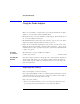
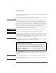
Connecting the N1022A Figure 1. Probe Channel Dialog Box 6 Click Close. You can now change the probe tips or probe attenuation. You can also perform a probe calibration. You can access information about probe attenuation and probe calibration in the Infiniium DCA Help system. Using modules with 2.4 mm electrical input The N1022A can be directly connected to any 86100-series or 83480-series with a 3.5 mm electrical channel input. You can also connect the probe adapter to a module with 2.
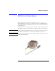
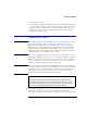
Static-Safe Workstation Static-Safe Workstation Electrostatic discharge (ESD) can damage or destroy electronic components. All work on electronic assemblies should be performed at a static-safe workstation. The following figure shows an example of a static-safe work station using two types of ESD protection: • Conductive table-mat and wrist-strap combination. • Conductive floor-mat and heel-strap combination. Figure 2.
Reducing ESD Damage Both types, when used together, provide a significant level of ESD protection. Of the two, only the table-mat and wrist-strap combination provides adequate ESD protection when used alone. To ensure user safety, the static-safe accessories must provide at least 1 MΩ of isolation from ground. Refer to Table 1 for information on ordering static-safe accessories.
Specifications and Regulatory Information Specifications and Regulatory Information This section lists specifications and characteristics and regulatory information of the probe adapter. Specifications The distinction between specifications and characteristics is described as follows: • Specifications describe warranted performance over the temperature range 0°C to +55°C and relative humidity <95% (unless otherwise noted).
Specifications Table 2. Environmental Specifications (2 of 2) Storage Humidity (type tested) 90% R.H. (non-condensing) at +65°C (+149°F), 24 hrs Shock (type tested) 30 g (half sine), 11 msec pulse Vibration (type tested) Random, 0.21g rms, 5 to 500 Hz, 10 minutes per axis Sine, 0.5g (0 to peak), 5 to 500 Hz, 1 octave/min Weight 200 g (7 oz) max Dimensions (excludes power cable) Height Weight Length 34 mm (1.34 in.) 38 mm (1.50 in.) 61 mm (2.4 in.) Power Cable Length 200 mm (7.9 in.
Specifications Table 3. Performance Specifications (2 of 2) Connector I/O (see figure below) DCA Connector Probe Connector Power Connector System Compatibility Custom ruggedized 3.5 mm connector Precision BNC connector Lemo push-pull 7-pin circular connector (works only with probe power) Compatible with Agilent 86100-series Infiniium DCA *Other Infiniium instruments in compliance with the Autoprobe interface can be added using the Probe dialog box located in the Infiniium graphical user interface.
Regulatory Information Regulatory Information Electrostatic Discharge Immunity - IEC 61000-4-2: 1995 passes criterion B. According to IEC 61000-4-2: 1995, system measurement may be affected when electrostatic discharges of 2 kV or more are applied to the outer surfaces of the N1022A probe adapter when it is connected as part of a measurement system. Compliance with Canadian EMC Requirements This ISM device complies with Canadian ICES-001.
Declaration of Conformity Declaration of Conformity 14
Service Service Service for the N1022A Active Probe Adapter is by replacement only. To order a new N1022A, contact your local Agilent Technologies Sales Office. Return the failed probe adapter to your local Agilent service center. If the probe adapter is still under warranty or is covered by an Agilent maintenance contract, it will be replaced under the terms of the warranty or contract.
Returning the N1022A Table 5. Probe Power Outputs Pin Supply 1 +3V 2 –3V 3 Offset 4 NC 5 and ring Probe ID 6 NC 7 RP 8 –12V 9 +12V Power Output Returning the N1022A When the probe adapter is returned to an Agilent service office for servicing, it must be adequately packaged and have a complete description of the failure symptoms attached. Please notify the service office before returning your probe adapter for service.
Agilent Technologies Service Offices CAUTION Cover electrical connectors to protect sensitive components from electrostatic damage. CAUTION Use original packaging or comparable. Instrument damage can result from using packaging materials other than the original materials. Never use styrene pellets as packaging material. They do not adequately cushion the instrument or prevent it from shifting in the carton. They may also cause instrument damage by generating static electricity.
Agilent Technologies Service Offices 18
Index A T Accessories, 4 Agilent offices, 17 temperature, 6 torque wrench, 4 C U CE mark, 3 cleaning, 2, 4, 17 CSA mark, 3 using, 4 D Declaration of Conformity, 14 E EMC requirements, 13 environmental specifications, 10 ESD reducing damage caused by ESD, 9 static-safe work station, 9 I inspecting, 4 ISM1-A, 3 N noise declaration, 13 noise requirements, 13 P performance specifications, 11 probe power outputs, 15 S sales and service offices, 17 service returning the probe adapter, 16 sales and s
Index Index 2