
User`s guide

14
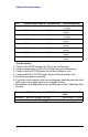
Calibration Testing Procedures
Test Bandwidth
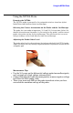
1 Connect the N2790A output to CH1 of the oscilloscope.
2 Connect adaptation 2 to the 81150A function generator output.
3 Connect the red N2790A probe tip to the red banana jack.
4 Connect the black N2790A probe tip to the black banana jack.
5 Load the appropriate setup file.
6 Verify the value complies with the oscilloscope limits listed in the table
below for each output signal at each probe setting.
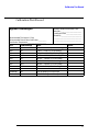
7 Record the value displayed on the oscilloscope in the Calibration Test
Record
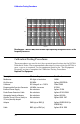
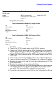
Test Calibrator Output Signal DC N2790A Setting 3458A Reading Limits
Gain +10 V 50:1
+196 mV ... +204 mV (\2%
of reading)
Gain +100 V 50:1
+1.96 V ... +2.04 V (\2% of
reading)
Gain +100 V 500:1
+196 mV ... +204 mV (\2%
of reading)
Gain +1000 V 500:1
+1.96 V ... +2.04 V (\2% of
reading)
Gain -10 V 50:1
-196 mV ... -204 mV (\2% of
reading)
Gain -100 V 50:1
-1.96 V ... -2.04 V (\2% of
reading)
Gain -100 V 500:1
-196 mV ... -204 mV (\2% of
reading)
Gain -1000 V 500:1
-1.96 V ... -2.04 V (\2% of
reading)
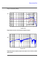
Test 81150A Output Signal N2790A Setting Oscilloscope setup &
limits
Bandwidth Sine wave, 100 MHz, 20 V
pp
50:1 Recall setup 1: > 2.8 div
Bandwidth Sine wave, 100 MHz, 20 V
pp
500:1 Recall setup 2: > 2.8 div