
User`s guide

13
Calibration Testing Procedures
Setup Files for testing
Test Gain
1 Connect the N2790A probe output to the N1022A adapter.
2 Connect the N1022A adapter to the 3458A multimeter via the outside
thread 3.5 mm (male) to 3.5 mm (female) adapter, SMA (m) to BNC (f)
adapter, BNC (m) to BNC (m) cable, and BNC (f) to banana (m) adapter.
3 Connect the N1022A adapter to the 1143A power supply via the 01143-
61602 cable.
4 Connect the red end of the N2790A probe to the calibrator HI output.
5 Connect the black end of the N2790A probe to the calibrator LO output.
6 Measure the output at 50:1 and 500:1 with the calibrator set to 0 V. This
is the probe offset.
7 Measure the output as shown in the table below.
8 Verify the value is between the 3458A limits listed in the table below for
each output signal at each probe setting. Note: These limits assume
zero offset. The limits should be adjusted for actual offset.
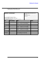
9 Record the value displayed on the 3458A in the Calibration Test Record
N2790A probe
Adapter BNC (f) to banana (m) Agilent 1251-2277
Adaptation 2 50 W termination + BNC (m) to
banana (f)
Description Minimum Requirements Part Number
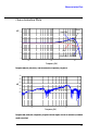
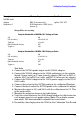
Setup for Bandwidth at 100 MHz, 50:1 Setting on Probe
CH1 ON
CH1 Sensitivity 100 mV/div, AC
Timebase 20 ns/div
BWL (Bandwidth Limiter) OFF
Trigger on CH1
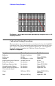
Setup for Bandwidth at 100 MHz, 500:1 Setting on Probe
CH1 ON
CH1 Sensitivity 10 mV/div, AC
Timebase 20 ns/div
BWL (Bandwidth Limiter) OFF
Trigger on CH1