N2790A Differential Voltage Probe User’s Guide For Safety, Regulatory, and publishing information, see the pages at the back of this book. © Copyright Agilent Technologies 2009 All Rights Reserved.
Contents Inspecting the Probe 3 Compatibility 4 Probe Parts Supplied 5 Characteristics and Specifications 6 Cleaning the Probe 8 Using the N2790A Probe 9 Service Strategy 10 Characterization Plots 11 Calibration Testing Procedures 12 2
Inspecting the Probe Inspecting the Probe ❏ Inspect the shipping container for damage. Keep a damaged shipping container or cushioning material until the contents of the shipment have been checked for completeness and the probe has been checked mechanically and electrically. ❏ Check the accessories. Any accessories that were supplied with the probe are listed in the “Probe Parts Supplied” section of this manual. • If the contents are incomplete or damaged, notify your Agilent Technologies Sales Office.
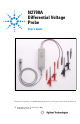
Inspecting the Probe N2790A Differential Voltage Probe The N2790A differential probe allows you to safely measure high-voltage floating circuits with the oscilloscope grounded. It is ideal for many applications such as motor speed controls, power supply designs, and electronic high-power converters. The N2790A offers sufficient dynamic range and bandwidth for your application to make the floating measurements found in high-speed power electronic circuits safely and accurately.
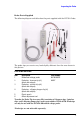
Inspecting the Probe Probe Parts Supplied The following diagram and table show the parts supplied with the N2790A Probe. 2 3 4 The probe tips you receive may look slightly different than the ones shown in this picture.
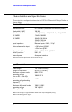
Characteristics and Specifications Characteristics and Specifications Characteristics and specifications for the N2790A Differential Voltage Probe are shown below. Electrical Characteristics Attenuation ratios Bandwidth (-3 dB)* Gain Accuracy* DC CMRR AC CMRR Input impedance Noise referenced to input Propagation Delay Switch positions Internal power 50:1 and 500:1 (Selectable via switch on probe.
Characteristics and Specifications Output Characteristics Output cable Maximum output voltage range Safety designed BNC cable \2.
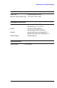
Cleaning the Probe W A R N I N G SHOCK HAZARD! These probes are designed for use with oscilloscopes that have a common terminal at GROUND POTENTIAL (in accordance with OSHA requirements and ! the National Electric Code). Exposed metallic surfaces of the probe and the oscilloscope MUST BE GROUNDED.
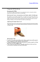
Using the N2790A Probe Using the N2790A Probe Powering the N2790A The N2790A probe is powered by the autoprobe interface found on Agilent InfiniiVision and Infiniium Series oscilloscopes. Selecting the Correct Attenuation on the Probe and the Oscilloscope The probe has two modes of operation, 50:1 and 500:1 attenuation. Select the desired attenuation on the probe (via the switch on the probe) and the correct probe attenuation setting on the oscilloscope.
Service Strategy Service Strategy For repair, calibration, and to ensure the N2790A performs to its warranted specifications, send the probe to an Agilent Service Center for calibration testing procedures. The probe should be tested once a year or as required by other standards. If repair is needed and the N2790A is under warranty, normal warranty services will apply. If the N2790A is not under warranty, repair costs will be applied.
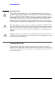
Characterization Plots Characterization Plots dB Vout 6 Vout/Vin 3 0 -3 Vin -6 -9 BW(-3dB) = 147 MHz 6 7 10 8 10 10 Frequency (Hz) Graph of dB(Vin), dB(Vout), and dB(Vout/Vin) frequency response -30 -40 -50 dB -60 -70 -80 10 7 8 10 Frequency (Hz) Graph of dB (Vout/Vin) frequency response when inputs driven in common (common mode rejection) 11
Calibration Testing Procedures 10 10 4 3 Vrms 10 10 2 1 10 0 10 1 10 2 10 3 10 4 10 5 10 6 10 7 10 8 Frequency Derating plot - above 2 MHz, the maximum input operating voltage decreases as the frequency increases. Calibration Testing Procedures These procedures are used to test the warranted specifications for the N2790A Differential Probe. The recommended calibration test interval for the N2790A is once a year or as required.
Calibration Testing Procedures Description N2790A probe Adapter Adaptation 2 Minimum Requirements Part Number BNC (f) to banana (m) 50 W termination + BNC (m) to banana (f) Agilent 1251-2277 Setup Files for testing Setup for Bandwidth at 100 MHz, 50:1 Setting on Probe CH1 ON CH1 Sensitivity 100 mV/div, AC Timebase 20 ns/div BWL (Bandwidth Limiter) OFF Trigger on CH1 Setup for Bandwidth at 100 MHz, 500:1 Setting on Probe CH1 ON CH1 Sensitivity 10 mV/div, AC Timebase 20 ns/div BWL (Bandw
Calibration Testing Procedures Test Gain Calibrator Output Signal DC N2790A Setting +10 V 50:1 3458A Reading Limits Gain +100 V 50:1 +1.96 V ... +2.04 V (\2% of reading) Gain +100 V 500:1 +196 mV ... +204 mV (\2% of reading) Gain +1000 V 500:1 +1.96 V ... +2.04 V (\2% of reading) Gain -10 V 50:1 -196 mV ... -204 mV (\2% of reading) Gain -100 V 50:1 -1.96 V ... -2.04 V (\2% of reading) Gain -100 V 500:1 -196 mV ... -204 mV (\2% of reading) Gain -1000 V 500:1 -1.96 V ... -2.
Calibration Test Record Calibration Test Record Agilent Technologies N2790A 100 MHz Differential Probe Serial No.:_______________________ Certification Date:_________________ Tested By:_______________________ Recommended Test Interval: 1 Year Recommended Date of Next Certification:_________ Certification Temperature:_____________________ _______________________________ _______________________________ Test Probe Settings Limits Gain 50:1 +196 mV ... +204 mV (\2% of reading) Gain 50:1 +1.96 V ..
Safety Notices This apparatus has been designed and tested in accordance with IEC Publication 1010, Safety Requirements for Measuring Apparatus, and has been supplied in a safe condition. This is a Safety Class I instrument (provided with terminal for protective earthing). Before applying power, verify that the correct safety precautions are taken (see the following warnings). In addition, note the external markings on the instrument that are described under "Safety Symbols.
Notices © Agilent Technologies, Inc. 2009 No part of this manual may be reproduced in any form or by any means (including electronic storage and retrieval or translation into a foreign language) without prior agreement and written consent from Agilent Technologies, Inc. as governed by United States and international copyright laws. Manual Part Number N2790-97000, June 2009 Print History N2790-97000, June 2009 Agilent Technologies, Inc.
A Agilent Technologies Printed in Japan Manual Part Number N2790-97000 *N2790-97000*