
User`s guide


Agilent N5161A/62A/81A/82A/83A MXG Signal Generators User’s Guide 23
Signal Generator Overview
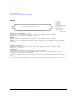
Rear Panel Overview – N5183A MXG
9. 10 MHz OUT
10. GPIB
This connector enables communication with compatible devices such as external controllers, and is
one of three connectors available to remotely control the signal generator (see also 11. LAN and
12. Device USB).
11. LAN
The signal generator supports local area network (LAN) based communication through this connector,
which enables a LAN–connected computer to remotely program the signal generator. The LAN
interface supports LXI; it does not support auto−MDIX. The signal generator is limited to 100 meters
on a single cable (100Base–T). For more information on the LAN, refer to the Programming Guide.
12. Device USB
Use this universal serial bus (USB) connector to connect a PC to remotely control the signal
generator.
13. Z AXIS OUTPUT
This female BNC connector supplies a +5 V (nominal) level during retrace and band–switch intervals
of a step or list sweep. During step or list sweep, this female BNC connector supplies a –5 V
(nominal) level when the RF frequency is at a marker frequency and intensity marker mode is on.
This signal is derived from an operational amplifier output so the load impedance should be greater
than or equal to 5 kohms.
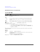
Connector female BNC Impedance nominally 50 Ω
Signal A nominal signal level greater than 4 dBm.
Connector Mini–B
USB Protocol Version 2.0