
User`s guide
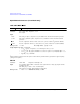


22 Agilent N5161A/62A/81A/82A/83A MXG Signal Generators User’s Guide
Signal Generator Overview
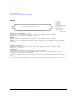
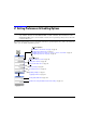
Rear Panel Overview – N5183A MXG
3. AM
4. FM
5. PULSE
6. TRIG IN
7. TRIG OUT
8. REF IN
In its factory default mode, the signal generator can detect a valid reference signal at this connector
and automatically switch from internal to external reference operation. See “Presetting the Signal
Generator” on page 42. With Option 1ER (flexible reference input), you must explicitly tell the signal
generator the external reference frequency you wish to use; enter the information through the front
panel or over the remote interface.
Connector female BNC Impedance nominally 50 Ω
Signal An externally supplied ±1 V
p
signal that produces the indicated depth.
Damage Levels 5 V
rms
and 10 V
p
Connector female BNC Impedance nominally 50 Ω
Signal An externally supplied ±1 V
p
signal that produces the indicated deviation
Damage Levels 5 V
rms
and 10 V
p
Connector female BNC Impedance nominally 50 Ω
Signal
Externally supplied: +1 V = on; 0 V = off
Damage Levels 5 V
rms
and 10 V
p
Connector female BNC Impedance high Z
Signal An externally supplied TTL or CMOS signal for triggering operations, such as point to point
in manual sweep mode or an LF sweep in external sweep mode.
Triggering can occur on either the positive or negative edge.
Damage Levels ≤ −0.5 and ≥ +5.5 V
Connector female BNC Impedance nominally 50 Ω
Signal A TTL signal that is high at the start of a dwell sequence, or when waiting for the point trigger in
manual sweep mode.
It is low when the dwell is over, or when the point trigger is received.
The logic polarity can be reversed.
This is a multiple use connector. For signal routing selections, see pages 50 and 127.
Connector female BNC Impedance nominally 50 Ω
Signal An externally supplied −3.5 to +20 dBm signal from a timebase reference that is within ±1 ppm.