
User`s guide


Agilent N5161A/62A/81A/82A/83A MXG Signal Generators User’s Guide 111
Optimizing Performance
Using Unleveled Operating Modes
Power Search Mode
NOTE The power search mode cannot be used with bursted signals input via the external IQ inputs.
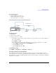
The MXG has three power search modes (for internal and external I/Q modulation) and four power
search references (for external I/Q modulation only). Refer to Figure 5- 23 on page 110.
Power search executes a routine that temporarily activates the ALC, calibrates the power of the
current RF output, and then disconnects the ALC circuitry.
Power Search Modes (Applies to External and Internal I/Q Modulation)
• Auto — A power search is executed at each frequency or power change, and at each change to the
AM, burst, pulse, or I/Q modulation state.
• Span — A power search is executed over a range of user- defined frequencies. The power search is
stored and used when the MXG is tuned within a user- defined range. After the Span softkey is
pressed, select either Full or User. If User is selected, then the start and stop frequencies need to
be selected.
• Manual — When Power Search is set to Manual, pressing Do Power Search executes the power search
calibration routine for the current RF frequency and amplitude. In this mode, if there is a change
in RF frequency or amplitude, you will need to press Do Power Search again.
Power Search References (Only applies to Internal I/Q Modulation)
The four Power Search References control the power search function. These four references select the
reference voltage used while the RF signal is being I/Q modulated. (Power search references are not
used for analog modulation: FM, φM, or pulse modulation.)
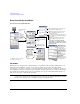
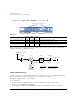
CAUTION If the power search reference has the incorrect RMS voltage, the output power will be
incorrect. Refer to Figure 5- 24, "Calculating the Output Power Error for a Single
Waveform Sample Point" and Figure 5- 25, “Calculating the RMS Voltage of the
Waveform.”
NOTE A successful power search is dependent on a valid power search reference.
• Fixed – Reference level is 0.5 Vrms.
This reference functions with internal, external IQ and bursted signals. This is the instrument’s
default setting.
• RMS – User provided reference level 0–1.414 Vrms placed in the Waveform Header. Refer to
“Saving a Waveform’s Settings & Parameters” on page 151.
This reference functions with internal IQ and bursted signals.
• Manual – User provided reference level 0–1.414 Vrms.
This reference functions with internal, external IQ and bursted signals.
• Modulated – Uses the I/Q modulation signal as the reference level.
This reference functions with internal or external IQ. It is not functional with bursted signals or
a signal with varying Vrms.