
Technical data
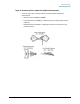


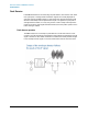
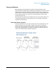

Table Of Contents
- EMC Measurement Application Measurement Guide
- Table of Contents
- 1 EMC Measurements
- 2 Conducted Emissions Measurements
- 3 Radiated Emissions Measurements
- A: Line Impedance Stabilization Networks (LISN)
- B: Antenna Factors
- C: Basic Electrical Relationships
- D: Detectors Used in EMI Measurements
- Glossary of Acronyms and Definitions
36
Detectors Used in EMI Measurements
Peak Detector
Peak Detector
Initial EMI measurements are made using the peak detector. This mode is much faster
than quasi-peak, or average modes of detection. Signals are normally displayed on
spectrum analyzers or EMC analyzers in peak mode. Since signals measured in peak
detection mode always have amplitude values equal to or higher than quasi-peak or
average detection modes, it is a very easy process to take a sweep and compare the
results to a limit line. If all signals fall below the limit, then the product passes and no
further testing is needed.
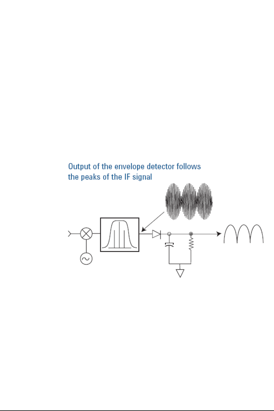
Peak detector operation
The EMC analyzer has an envelope or peak detector in the IF chain that has a time
constant, such that the voltage at the detector output follows the peak value of the IF
signal at all times. In other words, the detector can follow the fastest possible changes
in the envelope of the IF signal, but not the instantaneous value of the IF sine wave.