
Technical data
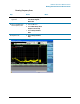
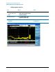
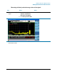

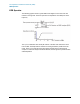


Table Of Contents
- EMC Measurement Application Measurement Guide
- Table of Contents
- 1 EMC Measurements
- 2 Conducted Emissions Measurements
- 3 Radiated Emissions Measurements
- A: Line Impedance Stabilization Networks (LISN)
- B: Antenna Factors
- C: Basic Electrical Relationships
- D: Detectors Used in EMI Measurements
- Glossary of Acronyms and Definitions
26
Line Impedance Stabilization Networks (LISN)
LISN Operation
LISN Operation
The following graphic shows a typical LISN circuit diagram for one side of the line
relative to earth ground. The chart represents the impedance of the DUT port versus
frequency.
The 1 μF in combination with the 50 μH inductor is the filter that isolates the mains
from the EUT. The 50 μH inductor isolates the noise generated by the EUT from the
mains. The 0.1 μF couples the noise generated by the EUT to the X-Series signal
analyzer or receiver. At frequencies above 150 kHz, the EUT signals are presented with
a 50Ω impedance.