
Technical data
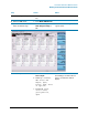
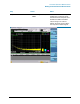
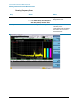
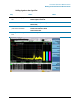
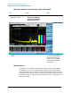
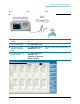
Table Of Contents
- EMC Measurement Application Measurement Guide
- Table of Contents
- 1 EMC Measurements
- 2 Conducted Emissions Measurements
- 3 Radiated Emissions Measurements
- A: Line Impedance Stabilization Networks (LISN)
- B: Antenna Factors
- C: Basic Electrical Relationships
- D: Detectors Used in EMI Measurements
- Glossary of Acronyms and Definitions

18
Radiated Emissions Measurements
Making Radiated Emission Measurements
Making Radiated Emission Measurements
CAUTION Before connecting a signal to the analyzer, make sure the analyzer can safely accept
the signal level provided. The signal level limits are marked next to the RF Input
connectors on the front panel.
See the AMPTD Y Scale menu for details on setting internal attenuation to prevent
overloading the analyzer.
Setting up and making an ambient measurement
This section demonstrates how to set up and perform radiated emission tests in the 30
to 300 MHz range.
NOTE Determine which regulatory requirements you will be testing to prior to starting the
following procedure.
Even if you only have access to a small shielded enclosure, you can still make valuable
measurement of your device. Emission signals found in the small chamber can save
you time later on in an open area test site by providing information about the
emissions of interest.
Step Action Notes
1 Test Set Up a. Arrange the antenna, DUT
and signal analyzer as
shown below:
Separate the antenna and the device under
test (DUT) as specified by the regulatory
agency requirements. If space is limited, the
antenna can be moved closer to the DUT
and you can edit the limits to reflect the
new position. For example, if the antenna is
moved from 10 meters to 3 meters, the
amplitude must be adjusted by 10.45 dB. It
is important that the antenna is not placed
in the near field of the radiating device.