
Technical data

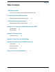

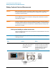
Table Of Contents
- EMC Measurement Application Measurement Guide
- Table of Contents
- 1 EMC Measurements
- 2 Conducted Emissions Measurements
- 3 Radiated Emissions Measurements
- A: Line Impedance Stabilization Networks (LISN)
- B: Antenna Factors
- C: Basic Electrical Relationships
- D: Detectors Used in EMI Measurements
- Glossary of Acronyms and Definitions
10
Conducted Emissions Measurements
Making Conducted Emission Measurements
Making Conducted Emission Measurements
CAUTION Before connecting a signal to the analyzer, make sure the analyzer can safely accept
the signal level provided. The signal level limits are marked next to the RF Input
connectors on the front panel.
See the AMPTD Y Scale menu for details on setting internal attenuation to prevent
overloading the analyzer.
CAUTION To prevent the signal analyzer input from possible damage that could be caused by
high level transient signals that could be produced by the LISN, it is recommended that
an 11947A Transient Limiter be used whenever conducted emissions testing is done
with the use of a LISN.
Setting up and making an ambient measurement
This section demonstrates how to set up and perform conducted emission tests in the
150 kHz to 30 MHz range.
NOTE Determine which regulatory requirements you will be testing to prior to starting the
following procedure.
Step Action Notes
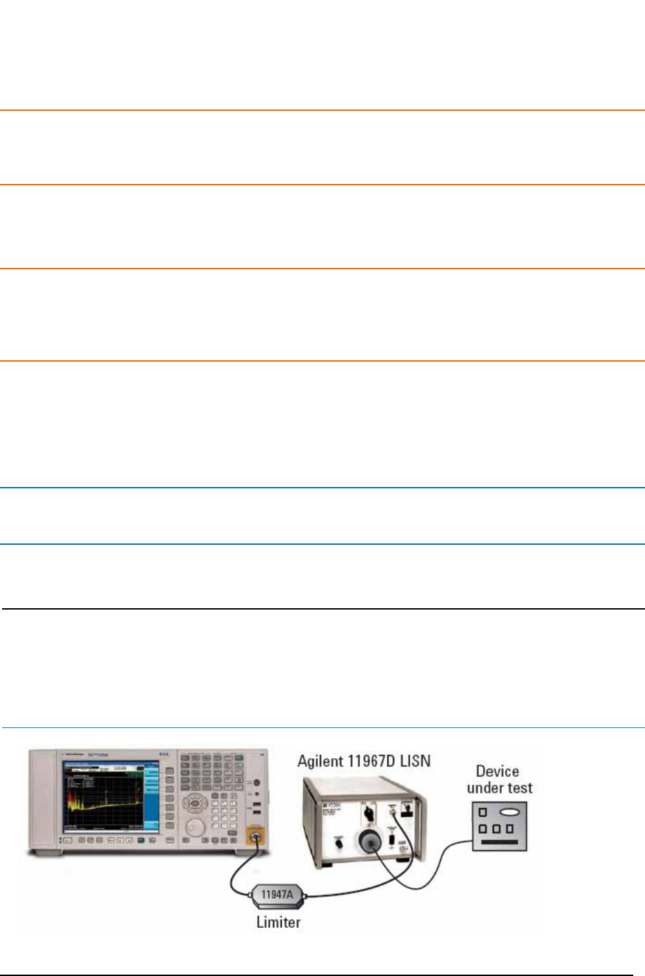
1 Test Set Up a. Connect device under test
(DUT), LISN, and Limiter to
the signal analyzer as
shown below:
Ensure that the power cord
between the DUT and the LISN is
as short as possible. The power
cord can become an antenna if
allowed to be longer than
necessary.