Agilent X-Series Signal Analyzer This manual provides documentation for the following analyzers: PXA Signal Analyzer N9030A MXA Signal Analyzer N9020A EXA Signal Analyzer N9010A CXA Signal Analyzer N9000A MXE EMI Receiver N9038A EMC Measurement Application Measurement Guide Agilent Technologies
Notices © Agilent Technologies, Inc. 2011 Manual Part Number No part of this manual may be reproduced in any form or by any means (including electronic storage and retrieval or translation into a foreign language) without prior agreement and written consent from Agilent Technologies, Inc. as governed by United States and international copyright laws. N6141-90002 Trademark Acknowledgements Microsoft® is a U.S. registered trademark of Microsoft Corporation. Windows® and MS Windows® are U.S.
Warranty This Agilent technologies instrument product is warranted against defects in material and workmanship for a period of one year from the date of shipment. During the warranty period, Agilent Technologies will, at its option, either repair or replace products that prove to be defective. For warranty service or repair, this product must be returned to a service facility designated by Agilent Technologies.
Contents Table of Contents 1 EMC Measurements The Role of Precompliance in the Product Development Cycle 2 Conducted Emissions Measurements Making Conducted Emission Measurements 10 3 Radiated Emissions Measurements Making Radiated Emission Measurements 18 Appendix A Line Impedance Stabilization Networks (LISN) LISN Operation 26 Types of LISNs 27 Appendix B Antenna Factors Field Strength Units 30 Appendix C Basic Electrical Relationships Appendix D Detectors Used in EMI Measurements Peak Detecto
Contents 6
EMC Measurements 1 EMC Measurements The EMC measurement application enables you to perform precompliance conducted and radiated emissions tests to both commercial and MIL-STD requirements. It provides better sensitivity, accuracy and reduces test margins, across the X-Series signal analyzers, so you can make more precise measurement.
EMC Measurements The Role of Precompliance in the Product Development Cycle The Role of Precompliance in the Product Development Cycle To ensure successful electromagnetic interference (EMI) compliance testing, precompliance testing has been added to the development cycle. In precompliance testing, the electromagnetic compatibility (EMC) performance is evaluated from design through production units.
Conducted Emissions Measurements 2 Conducted Emissions Measurements Conducted emissions testing focuses on emissions that are conducted along a power line that are generated by the device under test (DUT). The transducer that is typically used to couple the emissions of the power line to the signal analyzer is a line impedance stabilization network (LISN). The regulatory limits specify the maximum DUT emission energy, usually in dBμV, detected by the LISN.
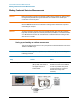
Conducted Emissions Measurements Making Conducted Emission Measurements Making Conducted Emission Measurements Before connecting a signal to the analyzer, make sure the analyzer can safely accept the signal level provided. The signal level limits are marked next to the RF Input connectors on the front panel. CAUTION See the AMPTD Y Scale menu for details on setting internal attenuation to prevent overloading the analyzer.
Conducted Emissions Measurements Making Conducted Emission Measurements Step Action Notes 2 Turn on the signal analyzer. a. Press the front-panel power key. 3 Select the EMC mode. a. Press Mode, EMI Receiver. 4 Open the scan table and select the desired range a. Press Meas Setup, Scan Table, Range 2, Range to On. Deselect any other range that has a green check. 5 Load Quasi-peak limit line a. Press Recall, Data, Limit Lines 1, Open.
Conducted Emissions Measurements Making Conducted Emission Measurements Step Action Notes 6 Load Average limit line a. Press Recall, Data, Limit Lines 2, Open. b. Scroll to EN 55022, Class A Cond, Average.lim, Open 7 Change EMI Average detector to compare to Limit Line 2 a. Press Meas Setup, Detectors (Measure) b. Select Detector, Detector 3 c. Limit for Δ, Limit 2, Enter 8 Show limit lines. a. Press Sweep Control, Start, Stop. 9 Load correction factors for the LISN a.
Conducted Emissions Measurements Making Conducted Emission Measurements Step Action Notes 13 Update the scan a. Press Sweep/Control, Start. View the ambient emissions (with the DUT off). If emissions above the limit are noted, the power cord between the LISN and the DUT may be acting as an antenna. Shorten the power cord to reduce the response to ambient signals.
Conducted Emissions Measurements Making Conducted Emission Measurements Running Frequency Scan Step Action Notes 1 Turn on the DUT and scan a. Turn the DUT on. Signals above the limit are designated in red. b. Press Meas Setup, Scan Sequence, Scan Only, Sweep/Control, Start. 2 Stop the scan a. Press Sweep/Control, Stop 14 This step will not be necessary if the measurement has completed the number of scans set or the desired time.
Conducted Emissions Measurements Making Conducted Emission Measurements Adding signals to the signal list Step Action Notes 1 Clear any existing signal list a. Press Meas Setup, Signal List, Delete Signals, Delete All 2 Switch to scan and search a. Press Meas Setup, Scan Sequence, Search Only 3 Set the search criteria to peak criteria and limits a. Press Meas Setup, More 1 of 2, Limits, Search Criteria, Peak Criteria and Limits 4 Add signals to the Signal List a.
Conducted Emissions Measurements Making Conducted Emission Measurements Measuring the Quasi-peak and average values of the signals Step Action Notes 1 Perform a Re-measure on all signals in the list a. Press Meas Setup, Scan Sequence, (Re)measure, (Re)measure, All Signals, Sweep/Control, Start. 2 Review the measurement results The delta to Limit Line values should all be negative. If some of the measurements are positive, there is a problem with conducted emissions from the DUT.
Radiated Emissions Measurements 3 Radiated Emissions Measurements Radiated emissions measurements are not as strainghforward as conducted emissions measurements. There is the added complexity of the ambient environment, which could interfere with measuring the emissions from a device under test (DUT).
Radiated Emissions Measurements Making Radiated Emission Measurements Making Radiated Emission Measurements Before connecting a signal to the analyzer, make sure the analyzer can safely accept the signal level provided. The signal level limits are marked next to the RF Input connectors on the front panel. CAUTION See the AMPTD Y Scale menu for details on setting internal attenuation to prevent overloading the analyzer.
Radiated Emissions Measurements Making Radiated Emission Measurements Step Action Notes 2 Turn on the signal analyzer. a. Press the front-panel power key. 3 Select the EMC mode. a. Press Mode, EMI receiver. 4 Open the scan table and select the desired range a. Press Meas Setup, Scan Table, Range 3 to On. 5 Set the attenuation and internal amplifier a. Press Meas Setup, Scan Table, More 1 of 3, Attenuation, 0, dB, Internal Preamp, Low Band. 19 Deselect any other range that has a green check.
Radiated Emissions Measurements Making Radiated Emission Measurements Step Action Notes 6 Load limit lines a. Press Recall, Data, Limit Lines 1, Open. b. Select My Documents, EMC limits and Ampcor, Open, Limits, Open, Files of type .lim, Open c. Scroll to EN 55022, Class A Rad (10m), Open. 7 Load correction factors for the biconical antenna a. Press Recall, Data, Amplitude Corrections 1, Open b. Select My Documents, EMC limits and Ampcor, Open, Ampcor, Open, Ampcor Files of type .ant c.
Radiated Emissions Measurements Making Radiated Emission Measurements Running Frequency Scan Step Action Notes 1 Clear any existing signal list a. Press Meas Setup, Signal List, Delete Signals, Delete All 2 Turn on the DUT and start frequency scan a. Turn the DUT on. b. Press Meas Setup, Scan Sequence, Scan Only c. Press Sweep/Control, Start. 3 Stop the scan a.
Radiated Emissions Measurements Making Radiated Emission Measurements Adding signals to the list Step Action Notes 1 Set the search criteria to peak criteria and limits a. Press Meas Setup, More 1 of 2, Limits, Search Criteria, Peak Criteria and Limits 2 Switch to search a. Press Meas Setup, Scan Sequence, Search Only 3 Add signals to the Signal List a. Press Sweep/Control, Start 22 This places the ambient signals in the Signal List.
Radiated Emissions Measurements Making Radiated Emission Measurements Measuring the Quasi-peak and average values of the signals Step Action Notes 1 Measure remaining signals a. Press Meas Setup, Scan Sequence, (Re)measure, (Re)measure All Signals. b.
Radiated Emissions Measurements Making Radiated Emission Measurements 24
Line Impedance Stabilization Networks (LISN) A: Line Impedance Stabilization Networks (LISN) A line impedance stabilization network serves three purposes: 1. The LISN isolates the power mains from the device under test. the power supplied to the DUT must be as clean a possible. Any noise on the line will be coupled to the X-Series signal analyzer and interpreted as noise generated by the DUT 2. The LISN isolates any noise generated by the EUT from being coupled to the power mains.
Line Impedance Stabilization Networks (LISN) LISN Operation LISN Operation The following graphic shows a typical LISN circuit diagram for one side of the line relative to earth ground. The chart represents the impedance of the DUT port versus frequency. The 1 μF in combination with the 50 μH inductor is the filter that isolates the mains from the EUT. The 50 μH inductor isolates the noise generated by the EUT from the mains. The 0.
Line Impedance Stabilization Networks (LISN) Types of LISNs Types of LISNs The most common type of LISN is the V-LISN. It measures the unsymmetric voltage between line and ground. This is done for both the hot and the neutral lines or for a three phase circuit in a “Y” configuration, between each line and ground. There are other specialized types of LISNs. A delta LISN measures the line-to-line or symmetric emissions voltage.
Line Impedance Stabilization Networks (LISN) Types of LISNs 28
Antenna Factors B: Antenna Factors 29
Antenna Factors Field Strength Units Field Strength Units Radiated EMI emissions measurements measure the electric field. The field strength is calibrated in dBμV/m.
Antenna Factors Field Strength Units Types of antennas used for commercial radiated measurements There are three types of antennas used for commercial radiated emissions measurements: • Biconical antenna: 30 MHz to 300 MHz • Log periodic antenna: 200 MHz to 1 GHz (the biconical and log periodic overlap frequency) • Broadband antenna: 30 MHz to 1 GHz (larger format than the biconical or log periodic antennas) 31
Antenna Factors Field Strength Units 32
Basic Electrical Relationships C: Basic Electrical Relationships The decibel is used extensively in electromagnetic measurements. It is the log of the ratio of two amplitudes. The amplitudes are in power, voltage, amps, electric field units and magnetic field units. decibel = dB = 10 log (P2/P1) Data is sometimes expressed in volts or field strength units. In this case, replace P with V2/R.
Basic Electrical Relationships 34
Detectors Used in EMI Measurements D: Detectors Used in EMI Measurements 35
Detectors Used in EMI Measurements Peak Detector Peak Detector Initial EMI measurements are made using the peak detector. This mode is much faster than quasi-peak, or average modes of detection. Signals are normally displayed on spectrum analyzers or EMC analyzers in peak mode. Since signals measured in peak detection mode always have amplitude values equal to or higher than quasi-peak or average detection modes, it is a very easy process to take a sweep and compare the results to a limit line.
Detectors Used in EMI Measurements Quasi-peak Detector Quasi-peak Detector Most radiated and conducted limits are based on quasi-peak detection mode. Quasi-peak detectors weigh signals according to their repetition rate, which is a way of measuring their annoyance factor. As the repetition rate increases, the quasi-peak detector does not have time to discharge as much, resulting in a higher voltage output. (See the following graphic.
Detectors Used in EMI Measurements Average Detector Average Detector The average detector is required for some conducted emissions tests in conjunction with using the quasi-peak detector. Also, radiated emissions measurements above 1 GHz are performed using average detection. The average detector output is always less than or equal to peak detection. Average detector operation Average detection is similar in many respects to peak detection.
Glossary of Acronyms and Definitions 39
Ambient level 1. The values of radiated and conducted signal and noise existing at a specified test location and time when the test sample is not activated 2. Those levels of radiated and conducted signal and noise existing at a specified test location and time when the test sample is inoperative. Atmospherics, interference from other sources, and circuit noise, or other interference generated within the measuring set compose the ambient level. Amplitude modulation 1.
Antenna terminal conducted interference Any undesired voltage or current generated within a receiver, transmitter, or their associated equipment appearing at the antenna terminals. Auxiliary equipment Equipment not under test that is nevertheless indispensable for setting up all the functions and assessing the correct performance of the EUT during its exposure to the disturbance. Balun A balun is an antenna balancing device, which facilitates use of coaxial feeds with symmetrical antennae such as a dipole.
Dipole 1. An antenna consisting of a straight conductor usually not more than a half-wavelength long, divided at its electrical center for connection to a transmission line. 2. Any one of a class of antennas producing a radiation pattern approximating that of an elementary electric dipole. Electromagnetic compatibility (EMC) 1.
Immunity 1. The property of a receiver or any other equipment or system enabling it to reject a radio disturbance. 2. The ability of electronic equipment to withstand radiated electromagnetic fields without producing undesirable responses. Intermodulation Mixing of two or more signals in a nonlinear element, producing signals at frequencies equal to the sums and differences of integral multiples of the original signals. Isotropic Isotropic means having properties of equal values in all directions.
RFI is the high frequency interference with radio reception. This occurs when undesired electromagnetic oscillations find entrance to the high frequency input of a receiver or antenna system. RFI sources Sources are equipment and systems as well as their components which can cause RFI. Shielded enclosure A screened or solid metal housing designed expressly for the purpose of isolating the internal from the external electromagnetic environment.