
Technical data

N7280
N7280N7280
N7280-
--
-90034
9003490034
90034-
--
-
Rev. A
Rev. ARev. A
Rev. A
System
SystemSystem
System Installation and Verification
Installation and Verification Installation and Verification
Installation and Verification
40
4040
40
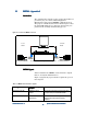
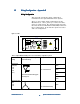
Figure 32: SMEMA Electrical interface schematic
SMEMA Connectors
SMEMA ConnectorsSMEMA Connectors
SMEMA Connectors
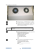
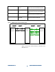
Figure 33 shows a connector with all pin numbers labeled,
and Table 5 shows the pin number and signal description
for the Medalist x6000 SMEMA connectors.
Figure 33: A typical SMEMA connector with pins numbered
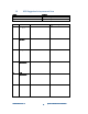
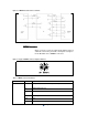
Table 5: SMEMA connector information
Connector Pin# Signal Description
1 Ready to Accept - Medalist x6000 is ready to receive a panel.
2 Floating signal return for (1)
3 Panel Available - Upstream equipment is ready to send a panel.
4 Electrical ground
5-13 N/A
Upstream SMEMA
14 Grounded shield