
Technical data

N7280
N7280N7280
N7280-
--
-90034
9003490034
90034-
--
-
Rev. A
Rev. ARev. A
Rev. A
System
SystemSystem
System Installation and Verification
Installation and Verification Installation and Verification
Installation and Verification
15
1515
15
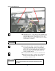
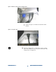
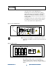
Figure 10: Inner barrier release
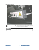
4
44
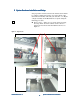
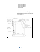
4 Check X-ray tower — Open the tower door with the 5/16
inch T-handle hex wrench that shipped with the system.
Check the SF6 pressure. It must be above 50 psi, and
should be between 55-65 psi. Verify all cables are firmly
seated in their connections.
There are two bolts in the tower door to prevent damage during shipment.
5
55
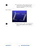
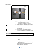
5 Subassemblies & PCBs — Inspect the condition of
electronics subassemblies. Inspect the individual
subassemblies and pc boards; look for any which may
have become unseated during shipping. Particular
attention should be paid to the system status and
control assembly (SSCA).
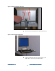
6
66
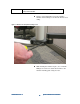
6 Verify that all the camera cables are still connected.
7
77
7 Monitor arm assembly — Unpack and assemble the
monitor arm. Set the height of the monitor arm
according to customer needs.
The x6000 will be delivered with the Monitor Arm Mount installed on the left front corner.
The customer should be consulted as to the location where they would like the monitor arm
installed. For right to left board flow, install the monitor arm on the left front corner of the
Agilent x6000.
NOTE
NOTE