
Technical data

N7280
N7280N7280
N7280-
--
-90034
9003490034
90034-
--
-
Rev. A
Rev. ARev. A
Rev. A
System
SystemSystem
System Installation and Verification
Installation and Verification Installation and Verification
Installation and Verification
10
1010
10
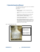
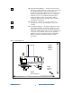
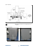
Figure 4: Stage rail alignment markings
10
1010
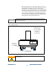
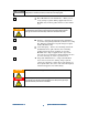
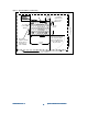
10 Adjust pads as required. This is done by turning the top
of the threaded shaft. See Figure 5. Use a level inside
the system on the granite base in various locations
rather than on the top of the system. Check x and y
orientation in all 4 corners.
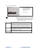
Verify that the system is level — After leveling the Medalist x6000, insure that the weight of the
Medalist x6000 is evenly distributed between all four mounting pads; be sure to evenly torque
the jacking bolts to the same torque. The actual torque will depend on the lubrication of the
threads with anti-seize but a relative value will be close to 22 ft/lbs. The actual value is not
critical as long as all four mounting pads are relatively close. Once the jack screws are torqued
correctly, tighten the associated jamb nut to prevent the jack screw from coming loose.
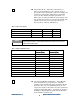
Use the spacer combination closest to the minimum for better system stability. For example if
you need a height of 88 centimeters, two B spacers would work but use one C instead; this
way the threaded shaft is closer to its bottom point. Using no spacers is not an option. It is
highly recommended that you use at least spacer C
If system height is not an issue install all spacers.
NOTE
Use these alignment marks
on the Medalist x6000
align the system with the
customer’s line.
(left side shown)
NOTE
NOTE