
User`s guide


Internetwork Monitor
Interpreting the Internetwork View
236 5967–9446
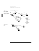
Figure 51 Handling Non-Routed Traffic
S1
S2
A
C
D
End-to-end traffic
(Network layer view),
with nodes A, B, C,
and D assigned to
segments S1 and S2
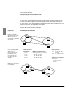
MAC layer view of
traffic, showing
pseudo-device
placement
S1
S2
A
B
C
D
P1
Network-Layer MAC-Layer Pseudo-Device
End Points End Points End Points
A↔B
(intrasegment pair: not relevant)
A↔CA↔CA↔P1, P2↔C
A↔DA↔DA↔P1, P2↔D
B↔DB↔DB↔P1, P2↔D
Corresponding MAC
addresses for
intersegment end-
point pairs A↔C,
A↔D, and B↔D
reveal no routers, so
pseudo-devices P1
and P2 are created for
segments S1 and S2
Intrasegment:
S1: A↔B, A↔P1,
B↔P1
S2: C↔P2, D↔P2
Segment-to-
Segment:
S1↔S2 =
A↔C + A↔D +
B↔D
P2
B