
User guide


8
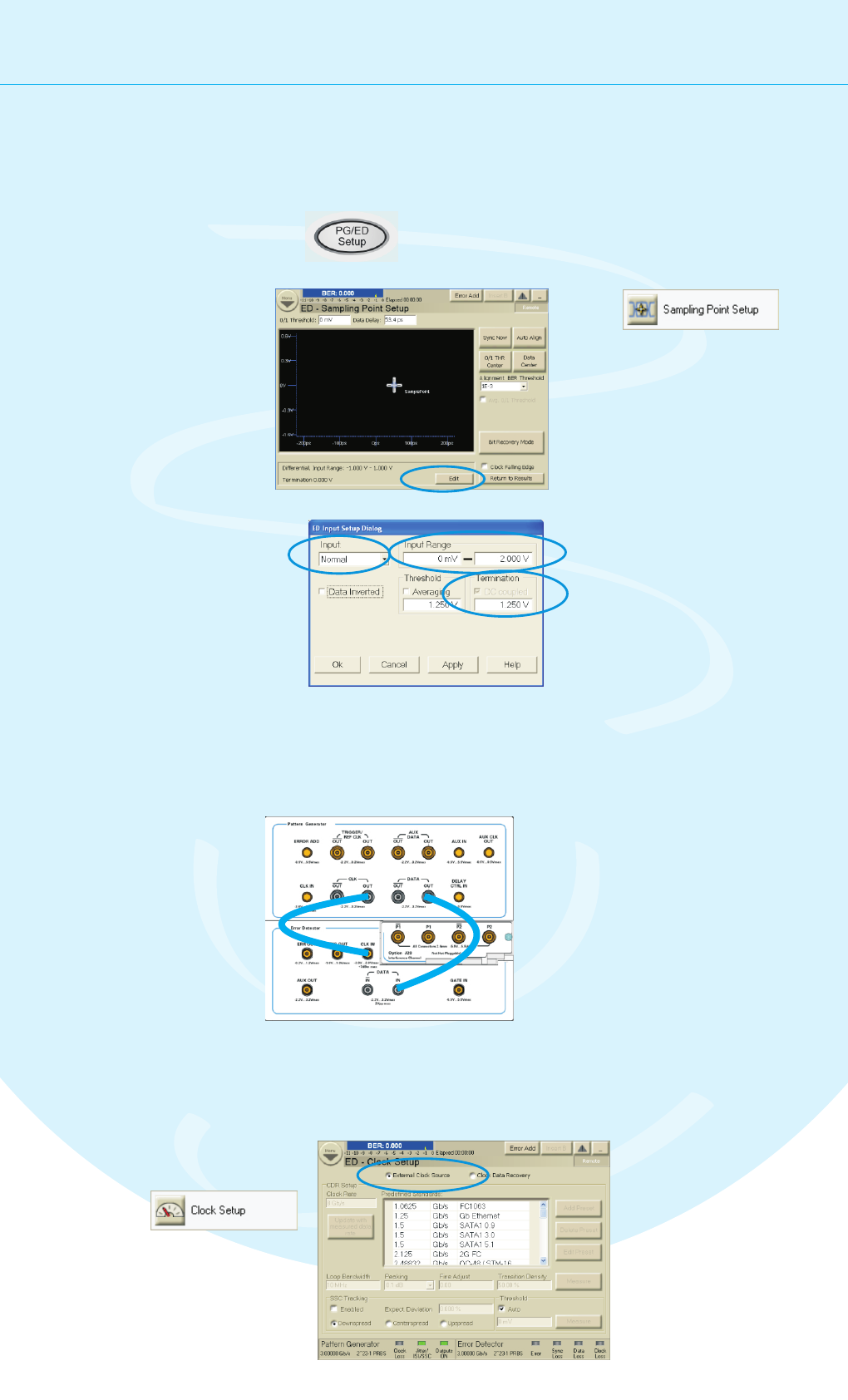
Setting up the Instrument
Setting up the Error Detector
Press the PG/ED button
twice to switch to the error
detector setup.
1
Click the Edit button.
3
Set the Input to Normal.
This means, we need only
one cable that will be
connected between the
pattern generator and
the data input port.
4
Enter the termination voltage
that matches the output
termination of the DUT, in our
case equal to the pattern
generator’s data output.
6
The next step is to set up the error detector’s inputs.
Set the Input Range so that
it covers both the high and
low voltage levels of the
data signal.
5
PG Data Out
Connecting the DUT
You can now connect the DUT. In our case you
just have to connect the following ports:
Defining the Clock
We have to make sure that the error detector
uses the clock from the pattern generator:
Select External Clock
Source as the source
for the clock signal.
2
ED Data In
PG Clock Out
ED Clock In
4
5
6
Switch to the
Sampling Point Setup.
2
Switch to the
Clock Setup.
1
3
2