
User guide


Preparing the Test
6
What Are We Testing?
Reset the instrument.
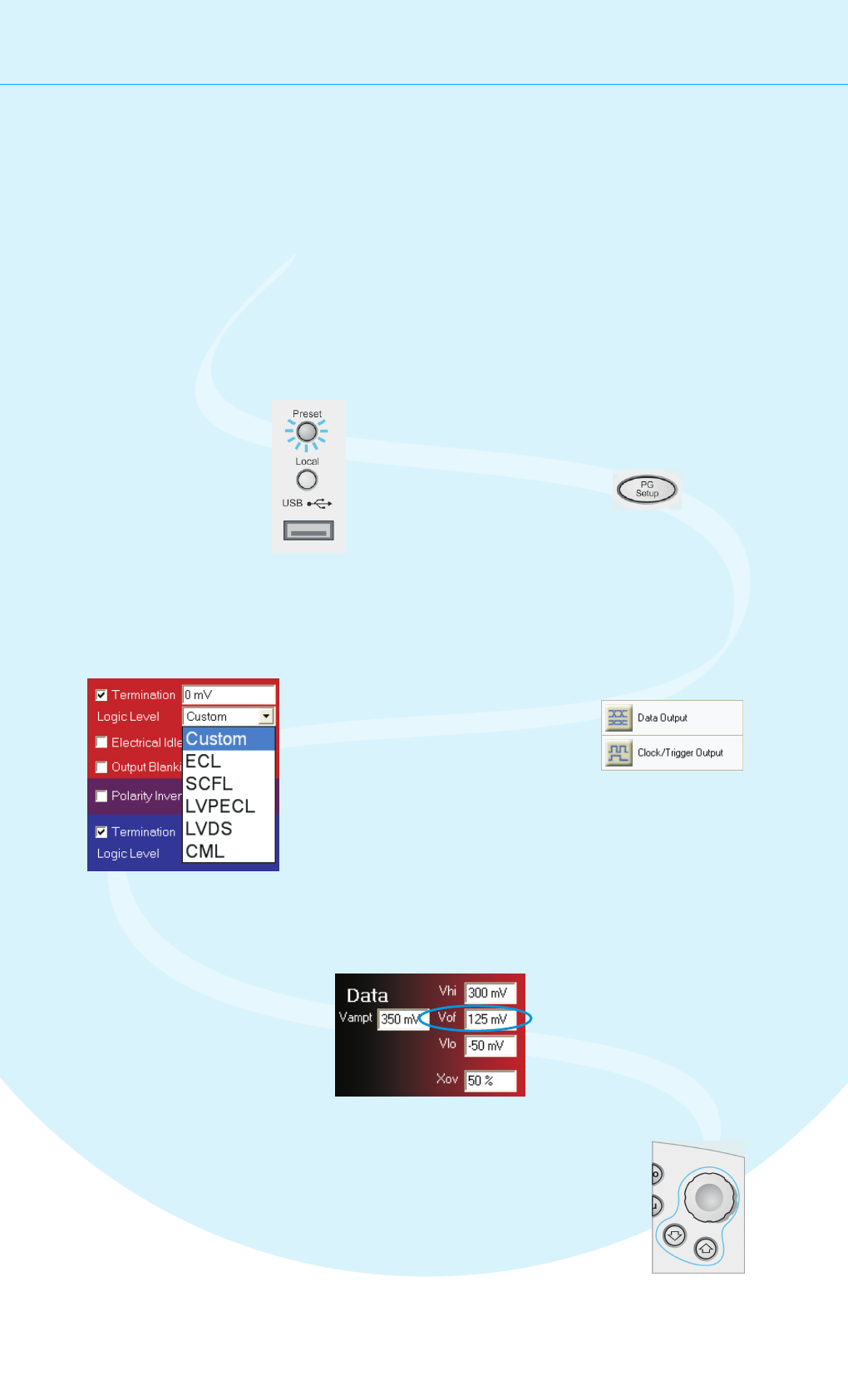
1
Use either navigation Menu or press
the button present on
the instrument to switch
to the PG Setup.
PG Setup
2
Now select the logic
family LVDS for the data
and clock port.
4
Let’s increase the
signal’s data offset by
100mV. Just tip the
offset field.
5
The quickest way to familiarize yourself with the instrument is to set up a
short test. You can test the BER on a cable. All you need for this test is an
APC/RPC cable for the data port connection and an APC/RPC-SMA adapter
cable to connect the PG clock output to the ED clock input.
Setting up the Pattern Generator
First we need to set up the pattern generator.
To keep things simple, let's set up LVDS logic
levels for both the data and clock output.
This sets all voltages
and parameters to
default values.
The pattern generator's
output ports are always active.
Therefore, you must be sure that
your device can handle these
ranges before you connect it.
You can change the output
signal parameters according
to the needs of your device.
Use the Up and Down
buttons below the knob
to position the cursor.
Turn the fine-tuning knob until
you have the desired value.
6
Click Data Output for Data Output
Setup, or click Clock/Trigger
Output for Clock Output Setup.
3