
Technical data


Setting Up Data Points
The Jitter Tolerance Characterization test generates jitter with varying amplitudes.
The condition for proceeding from one amplitude to the next and the direction
(upwards or downwards) can be specified, as well as the step size. The test for a
given frequency stops when the measured BER exceeds (or falls below) the target
BER.
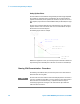
The test can be swept automatically over a wide frequency range. Test result is
the jitter tolerance curve of the device. This curve is constructed from the pass/
fail transitions of the measured points.
The following figure shows an example.
Besides the target bit error ratio, you need to specify the verification method and
the positioning of the measured points. The latter can be done in manifold ways.
Running JTol Characterization - Procedures
The following code indicates how you could set up and run the Jitter Tolerance
Characterization test using SCPI.
N O T E
The Jitter Tolerance Characterization measurement displayed in the user interface
cannot be controlled remotely. When you set up a program to run a Jitter Tolerance
Characterization measurement remotely, a separate measurement object is
created. Any programmatical changes to this measurement object will not be
reflected in the user interface.
3 Recommended Programming Techniques
40 Agilent J-BERT N4903B High-Performance Serial BERT