
Technical data


SENSe2:FREQuency:CDR?
Enables or disables clock data recovery (CDR) mode.
In CDR mode, the CDR has to recover the clock from the incoming data. To do this,
the hardware has to decide whether the voltage at the input connector is a logical
'1' or '0' and then recover the clock from the detected transitions.
Because the regular threshold voltage is not only used to determine the optimum
sampling for the data, but also to perform measurements such as eye diagram or
output level measurements, it is not possible to use it for the clock recovery.
For this reason, the clock recovery circuitry has it's own comparator for the
incoming data. This comparator also needs to know the threshold voltage (0/1
decision threshold).
The threshold voltage can be derived from the input signal via a low-pass filter.
This will work fine for most applications. But applications that do not provide a
continuous data stream at the input (for example, any application using bursts)
cannot use this low-pass filter, because the threshold voltage will drift from the
correct level when there is no input. In such cases, the threshold can be specified
manually. It is then no longer derived from the input signal (see the following
figure). The manually set threshold voltage must of course be within the input
range.
The difference between the data path and the CDR path is that the comparator of
the CDR is always single-ended. Thus, this comparator always needs a threshold
voltage that lies between the high and low levels of the incoming signal.
The differential threshold of the data path comparator has no relation to the single-
ended threshold of the CDR path comparator. This means that in differential mode,
the two thresholds will be different and in single-ended mode (either normal and
complement) they will/can be equal (except during measurements).
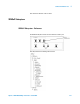
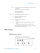
The following figure shows a simplified block diagram. It does not reflect the
different input modes (especially the differential case), but it matches both single-
ended cases.
5 SCPI Command Reference
274 Agilent J-BERT N4903B High-Performance Serial BERT
Description
How Does Clock Data Recovery Work?