S Agilent J-BERT N4903B High-Performance Serial BERT Programming Guide s Agilent Technologies
Notices © Agilent Technologies, Inc. 2014 Manual Part Number No part of this manual may be reproduced in any form or by any means (including electronic storage and retrieval or translation into a foreign language) without prior agreement and written consent from Agilent Technologies, Inc. as governed by United States and international copyright laws. N4903-91031 Edition Release Edition, June 2014 Printed in Germany Agilent Technologies, Deutschland GmbH Herrenberger Str.
Contents 1 Programming Basics Programming Basics - Concepts Before You Begin 8 Before You Begin - Concepts 7 8 Instrument Behavior 10 Instrument Behavior - Reference 2 10 A Typical SerialBERT Program A Typical Serial BERT Program - Concepts Prerequisites 13 Prerequisites - Concepts 13 13 Initializing the Connection to the SerialBERT 14 Initializing the Connection - Concepts 14 Initializing the Connection - Procedures 14 Working with the IVI-COM Objects 15 Working with the IVI-COM Objects - Concepts
Allowing the Serial BERT to Settle 22 Allowing Serial BERT to Settle - Concepts 22 Allowing Serial BERT to Settle - Procedures 22 Reading the Serial BERT's Status 24 Reading the Serial BERT's Status - Concepts 24 Reading the Serial BERT's Status - Procedures 27 Reading the Serial BERT's Status - Reference 27 Running the Fast Eye Mask 35 Running the Fast Eye Mask - Concepts 35 Running the Fast Eye Mask - Procedures 36 Running the Eye Diagram 38 Running the Eye Diagram - Concepts 38 Running the Eye Diagram -
SCPI Command Reference Serial BERT Subsystems 89 IEEE Commands 91 IEEE Commands – Reference 91 SOURce[1] Subsystem 98 SOURce[1] Subsystem - Reference 98 OUTPut[1] Subsystem 133 OUTPut[1] Subsystem - Reference 133 SOURce9 Subsystem 160 SOURce9 Subsystem - Reference 160 SOURce2 Subsystem 165 SOURce2 Subsystem - Reference 165 OUTPut2 Subsystem 171 OUTPut2 Subsystem - Reference 171 SOURce3 Subsystem 173 SOURce3 Subsystem - Reference 173 SOURce5 Subsystem 183 SOURce5 Subsystem - Reference 183
PLUGin Subsystem 312 PLUGin Subsystem - Reference 312 STATus Subsystem 316 STATus Subsystem - Reference 316 SYSTem Subsystem 330 SYSTem Subsystem - Reference 330 MEASure Subsystem 338 MEASure Subsystem - Reference TEST Subsystem 402 TEST Subsystem - Reference Index 6 338 402 405 Agilent J-BERT N4903B High-Performance Serial BERT
S Agilent J-BERT N4903B High-Performance Serial BERT Programming Guide 1 Programming Basics Programming Basics - Concepts This document provides the information you need for programming the Serial BERT using the Agilent IO Libraries Suite. Familiarity with the Agilent IO Libraries Suite is instrumental in understanding remote programming of the Serial BERT. See the user documentation delivered with the Agilent IO Libraries Suite for information on how to use them.
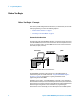
1 Programming Basics Before You Begin Before You Begin - Concepts This section provides background information that you need before you start with remote programming. It contains the following subjects: • “Communication Overview” on page 8 • “Connecting to the Serial BERT” on page 9 Communication Overview Communication with the Serial BERT is based on a host-client protocol. The server is the Serial BERT itself, the host is the remote client.
Programming Basics 1 Connecting to the Serial BERT To communicate with the Serial BERT from a remote computer, the Agilent IO Libraries Suite must be installed on this computer. NOTE The following descriptions only provide you with the information you need from the Serial BERT. For complete instructions on how to establish connections to the Serial BERT, refer to the user documentation delivered with the Agilent IO Libraries Suite.
1 Programming Basics Instrument Behavior Instrument Behavior - Reference The Serial BERT behaves as follows when it is turned on (or after a power-cycle): Instrument Mode At power on, the Serial BERT will return to the same mode as it was powered down. Normally, once it has booted, the Serial BERT is ready for either front panel operation or remote operation.
1 Programming Basics You can identify whether the error detector or pattern generator is overheating by running a self-test on both devices. To run a self-test: See also the Serial BERT User Guide (or online Help) for details. Operation Modes The Serial BERT can be operated in one of two modes: local or remote. Local Mode In local mode, all the front panel controls are responsive and control the instrument.
1 Programming Basics 12 Agilent J-BERT N4903B High-Performance Serial BERT
S Agilent J-BERT N4903B High-Performance Serial BERT Programming Guide 2 A Typical SerialBERT Program A Typical Serial BERT Program - Concepts The Serial BERT can be controlled by a remote program using the IVI-COM driver. The sections of this Help provide you with information you can use to quickly get started with your first program. The examples here are written for Visual Basic 6.0, but can also be ported to any programming language supported by IVI-COM.
2 A Typical SerialBERT Program • IVI-COM driver installed • Configured IO connection to the Serial BERT (you should be able to find the Serial BERT with the I/O libraries VISA assistant) Initializing the Connection to the SerialBERT Initializing the Connection - Concepts The first step in setting up a program for controlling the Serial BERT is to create an object that corresponds to the instrument.
A Typical SerialBERT Program 2 True, True,"QueryInstrStatus=true") End Sub Private Sub Form_Unload(Cancel As Integer) myBERT.Close End Sub Working with the IVI-COM Objects Working with the IVI-COM Objects - Concepts The Serial BERT IVI-COM driver uses a hierarchical class structure that follows the build up of the instrument. For example, the instrument itself is represented by the class AgilentN490x. The pattern generator is represented by the class IAgilentN490xPG.
2 A Typical SerialBERT Program Set myED = .EDs.Item(EDName) Set myEDDataIn = myED.Input.DataIns.
A Typical SerialBERT Program 2 myEDDataIn.Synchronisation.SyncNow End Sub Setting Up a Pattern The following code shows you how to set up a pattern. It additionally shows a small function that converts strings into arrays that Visual Basic can handle. Private Sub SetUpPattern() Dim myPattern As AgilentBertLib.IAgilentBertLocalPatternfile ' Use local pattern 13 to save the pattern files ' to a different location Set myPattern = myBERT.LocalPatternfiles._ Item(myBERT.LocalPatternfiles.
2 A Typical SerialBERT Program myPattern(ix - 1) = CByte("&H" & Mid(DataString, ix, 1)) Case AgilentBertEDPatternFormatRaw myPattern(ix - 1) = CByte(Mid(DataString, ix, 1)) End Select Next SetPatternData = myPattern End Function 18 Agilent J-BERT N4903B High-Performance Serial BERT
S Agilent J-BERT N4903B High-Performance Serial BERT Programming Guide 3 Recommended Programming Techniques Recommended Programming Techniques - Concepts This chapter provides some recommended techniques you should use when programming the Serial BERT. Output Protection Output Protection The pattern generator's Data, Clock, Aux Data and Trigger/Ref Clock Out ports must be terminated with 50 Ω if they are not connected. Termination of output ports improves the test performance.
3 Recommended Programming Techniques • VHigh = VTerm + 1 V • VLow = VTerm + 0.9 V If the port is correctly terminated while in this state, the output levels are returned to the original levels. NOTE If VTerm is greater than 1.5V, the protection algorithm is not active. In an automated test environment, the algorithm may introduce up to 200ms delay time when switching the DUT. You can avoid the protection algorithm from becoming active when switching the DUT (and thus enhance the test throughput).
3 Recommended Programming Techniques Controlling the Output Levels Controlling the Output Levels - Concepts When the output levels are changed at the Serial BERT's data and clock output ports, four parameters are changed: • Vhi • Vlo • Vampt • Voffs The Serial BERT groups these parameters into "pairs" (Vampt/Voffs, Vhi/Vlo). If one of these values is modified, its "partner" remains constant, and the values in the other pair are modified accordingly.
3 Recommended Programming Techniques This has the same effect. Allowing the Serial BERT to Settle Allowing Serial BERT to Settle - Concepts When patterns are sent to the pattern generator or error detector, the Serial BERT requires some time to settle before. The following topics explain how the instruments react to pattern changes. How Pattern Changes Affect the Pattern Generator The Serial BERT requires some time to change the patterns at the pattern generator and error detector.
Recommended Programming Techniques 3 Dim myPG As AgilentN490x.Interop.IAgilentN490xPG2 Set BERTStatus = myBERT.Status Set myED = myBERT.EDs.Item("ED1") Set myPG = myBERT.PGs.Item("PG1") ' First enable the register of interest: ' Operation register, bit 13, positive transition BERTStatus.Register(AgilentN490xStatusRegisterOperation, _ AgilentN490xStatusSubRegisterEnable) = &H2000 BERTStatus.Register(AgilentN490xStatusRegisterOperation, _ AgilentN490xStatusSubRegisterPositiveTransition) = &H0 BERTStatus.
3 Recommended Programming Techniques } while(question_reg() && QUESTION_REG_10); If Question_reg returns a value that includes bit 10 ("1024"), this is an indication that the error detector has not yet synchronized to the new pattern. In this case, the instrument has not yet settled. NOTE File accessing, especially for large files can take some time. Control programs must be prepared for time-outs of this size.
3 Recommended Programming Techniques How the Serial BERT Uses Status Registers You can determine the state of certain instrument hardware and firmware events and conditions by programming the status register system. The following subsections provide you with details about the Serial BERT's status system. Overview of the Serial BERT's Status System The Serial BERT has status reporting features that give important information about events and conditions within the instrument.
3 Recommended Programming Techniques The condition register continuously monitors the hardware and firmware status of the instrument. There is no latching or buffering for a condition register. It is updated in real time. This register is read by the CONDition? SCPI commands. • Negative Transition The negative transition register specifies the bits in the condition register that will set corresponding bits in the event register when the condition bit changes from 1 to 0.
Recommended Programming Techniques 3 Reading the Serial BERT's Status - Procedures See “Starting ELOC and Verifying that it is Running” on page 47 for an example of how to access the registers in IVI-COM. See “Preparing the Registers (SCPI)” on page 50 for a SCPI example. Reading the Serial BERT's Status - Reference NOTE Depending on the options of your Serial BERT, some of the status bits may not be valid for your instrument.
3 Recommended Programming Techniques Status Byte The Status Byte is the summary register to which the other registers report. Each reporting register is assigned a bit in the Status Byte Register. The bits in the Status Byte byte have the following meaning: Table 1 Bit 6 Bit Mnemonic Description 0 Not used 1 Not used 2 EAV Error available: The error queue contains at least one message.
3 Recommended Programming Techniques • *STB? If the register is read using the common command *STB? , bit 6 is referred to as the master summary bit or MSS bit. This bit indicates that the instrument has requested service. The MSS bit is not cleared when the register is read using the *STB? command. It always reflects the current status of all the instrument's status registers.
3 Recommended Programming Techniques Table 2 NOTE Bit Mnemonic Description 4 EXE Execution error bit. It is set when a command (GPIB instrument specific) cannot be executed due to an out of range parameter or some instrument condition that prevents execution. 5 CME Command error bit. It is set whenever the instrument detects an error in the format or content of the program message (usually a bad header, missing argument, or wrong data type etc.).
Recommended Programming Techniques 3 Table 3 Bit Mnemonic Description 0 ERR DET Clock loss condition at the error detector. 1 PAT GEN Clock loss condition at the pattern generator. 2-15 Not used Symbol Mode Register The Symbol Mode Register group indicates whether the error detector has experienced a 10B symbol alignment loss or 10B symbol alignment done. The output of this register sets bit 12 (Symbol Mode) in the Questionable Status Register.
3 Recommended Programming Techniques Table 5 32 Bit Mnemonic Description 0 DATA LOSS This bit is set when the data source is turned off, not connected, or the cables or device is faulty. This bit can also set when the 0/1 threshold is not in the eye limits of the incoming data signal. In this last case, use Auto Align or select Avg 0/1 Threshold.
Recommended Programming Techniques 3 Table 5 NOTE Bit Mnemonic Description 8 UNCAL This bit is set when the serial number of the installed pattern generator or error detector does not match the calibration file in the instrument. 9 Not used 10 SYNC LOSS 11-15 Protection Circuit 12 Symbol Mode 13-15 Not used This bit is set when the error detector pattern does not match the incoming data pattern or the BER of your device is higher than the sync threshold.
3 Recommended Programming Techniques Table 6 34 Bit Mnemonic Description 3 OVERHEAT The pattern generator or error detector has a higher-than-normal temperature. 4 GATE ON An accumulated measurement is in progress. 5-6 Not used 7 GATE ABORT Indicates that the repetitive accumulation period was aborted. 8 BIT ERR The instrument has detected a bit error. 9-10 Not used 11 CLK/DATA CTR Indicates that the clock/ data alignment is in progress.
Recommended Programming Techniques NOTE 3 Depending on the options of your Serial BERT, some of the status bits may not be valid for your instrument. See the User Guide for a description of the available options. Running the Fast Eye Mask Running the Fast Eye Mask - Concepts NOTE This topic is only valid for instruments with the Fast Eye Mask option. See the User Guide for a description of the available options for your instrument.
3 Recommended Programming Techniques Setting Up Data Points When you create a measurement object, the object is set up by default with six symmetrically placed data points, as shown in the following figure: These settings can be changed, and up to 32 measurement points can be defined. For this, you would first change the number of measurement points, and then specify each of the points as required.
Recommended Programming Techniques 3 2 Note that the returned number (handle) has to be used as a suffix in each of the subsequent SCPI commands to address the measurement. 2 Define how many bits are to be compared: meas:fem2:par:mcb 1.0E+6 3 Specify how many errors at one point move the measurement to the next point: meas:fem2:par:merr 1 4 Now enable error mode: meas:fem2:par:merr:mode ENA 5 Specify the allowed bit error rate: meas:fem2:par:pfcr 1.
3 Recommended Programming Techniques 0 ... meas:fem2:poin:pass? 6 0 In our example, points 1 and 6 failed, the other points passed. 4 Specify how the timing resolution is to be reported: meas:fem2:par:tres:type UINT 5 Specify how the threshold is to be reported: meas:fem2:par:thr:type ABS 6 Check the timing resolution and threshold at points 1 and 6: meas:fem2:par:point? 1 -4.0E-1,1.525000035763E-1 meas:fem2:par:point? 6 1.6E-1,-4.
3 Recommended Programming Techniques Running the Eye Diagram - Procedures The following code indicates how you could set up and run the Eye Mask using SCPI. NOTE The Eye Diagram measurement displayed in the user interface cannot be controlled remotely. When you set up a program to run an Eye Diagram measurement remotely, a separate measurement object is created. The user interface does not reflect any change in program for this measurement object.
3 Recommended Programming Techniques Setting Up Data Points The Jitter Tolerance Characterization test generates jitter with varying amplitudes. The condition for proceeding from one amplitude to the next and the direction (upwards or downwards) can be specified, as well as the step size. The test for a given frequency stops when the measured BER exceeds (or falls below) the target BER. The test can be swept automatically over a wide frequency range. Test result is the jitter tolerance curve of the device.
Recommended Programming Techniques 3 Prepare the Measurement To create the measurement object and prepare the measurement: 1 Create the session: meas:jtol:char:cre? 7 Note that the returned number (handle) has to be used as a suffix in each of the subsequent SCPI commands to address the measurement. 2 Specify the target bit error ratio: meas:jtol:char7:par:btes:tber 1.
3 Recommended Programming Techniques 1.0E+0 Evaluate the Results To evaluate the results: 1 Get the number of points measured: meas:jtol:char7:fetc:data:ava? 54 2 Ask for the DUT capability: meas:jtol:char7:fetc:data:cap? DUT This returns for each of the measured frequencies the maximum jitter amplitude the DUT could stand without exceeding the target BER. These are the values that form the jitter tolerance curve.
Recommended Programming Techniques 3 Restrictions for Error Location Capture Error Location Capture is subject to the following restrictions: • Only memory-based patterns with a unique 48-bit pattern (detect word) are allowed. • The error detector must be aligned to the incoming stream. • No alignment features can run during error location capture: Auto Align, 0/1 Threshold Center, Data Center • No other advanced measurement (Output Timing, Output Levels, etc.) can be running.
3 Recommended Programming Techniques The Operation Status register should catch negative transitions on the ERR LOC CAPTURE bit (bit 14). 2 Check the status registers to see if Error Location Capture has stopped. 3 If it has stopped, check the status of Error Location Capture. It could have either been aborted or successful. See also “Handling the Results” on page 45 for more information. How to Abort Error Location Capture Error Location Capture runs until it detects an error and stops.
3 Recommended Programming Techniques Measurement Status To query the status of the Error Location Capture measurement: • Use the following commands: – IVI-COM: IAgilentN490xEDErrorLocation.ReadState – SCPI: SENSe1:ELOCation:VERBose? • In the Operation Status register, check the Error Location Capture bit (bit 14) : – If the bit is high, the measurement is running. – If the bit is low, the measurement is not running. It may be not started yet, successfully finished, or aborted.
3 Recommended Programming Techniques How to Handle Run Errors Errors in Error Location Capture are handled differently than standard instrument errors: • Errors caused by starting or stopping Error Location Capture are put in the standard error queue. • Internal run errors caused during Error Location Capture are neither put into the standard error queue nor reported by the status register's error flag. In such a case, the response to SENS:ELOC:VERB? is ELOC__FAILED.
Recommended Programming Techniques 3 Private myStatusByte As Integer Private myOperReg As Long Starting ELOC and Verifying that it is Running Sub Start_And_Verify_ELOC() Set myED = myBert.EDs.Item("ED1") Set myEDDataIn = myED.Input.DataIns.Item("EDDataIn1") Set myPG = myBert.PGs.Item("PG1") Set myPGDataOut = myPG.Outputs.Item("PGOutput1") Set myELOC = myEDDataIn.ErrorLocation Set myStatus = myBert.Status ' Reset the instrument: myBert.Utility.
3 Recommended Programming Techniques AgilentN490xStatusRegisterOperation, _ AgilentN490xStatusSubRegisterEnum. AgilentN490xStatusSubRegisterEvent) If (myOperReg And &H4000) <> 0 Then Exit Do End If 'DoEvents() Loop While True ' We now know that Error Location Capture is running. End Sub Setting Up the Status Registers Manually Stopping ELOC Private Sub Set_Up_Registers_For_Stop() ' Set the operation register to trigger when Error Location Capture(stops) With myStatus ' First clear the registers: .
Recommended Programming Techniques 3 If myELOC.ReadState = AgilentN490xEDErrorLocationStateEnum. AgilentN490xEDErrorLocationStateAborted Then ' Any code for verifying the manual stopping Else ' Any code for handling other states End If End Sub Manually Inserting an Error Before injecting the error you have to reset the status registers: Private Sub Insert_Error_and_Get_Results() 'Set the status registers to trigger when error is inserted With myStatus 'First clear the status registers: .
3 Recommended Programming Techniques If myELOC.ReadState = AgilentN490xEDErrorLocationStateEnum. AgilentN490xEDErrorLocationStateSuccess Then ' Read the results myELOC_CountedErrors = myELOC.ReadCount ' Should be 1 myELOC_FirstBitError = myELOC.BitAddress ' Location of errored bit Else ' Any code for handling problems End If End Sub Running ELOC in SCPI The following is an example for running ELOC in SCPI with a memory based pattern and a stimulated error.
3 Recommended Programming Techniques Alternatively, you can set up a loop and wait until the OPER bit (bit7) of the status byte is set (*STB?). Then check the Operation status register (STATus:OPERation?). If bit14 is set, ELOC has started.
3 Recommended Programming Techniques To calculate the captured pattern, XOR the bits from pattern A with the bits from pattern B. See also “Handling the Results” on page 45 for more information.
Recommended Programming Techniques 3 • Locate the corresponding status register. • Set the transition filter to pass the chosen transition of that event. • Set the enable register from that register group to pass that event to set the summary bit in the Status Byte Register. • Set the Status Byte Enable Register to generate an SRQ on the chosen summary bit being set. Using Interrupts - Procedures The process of using interrupts is best explained by looking at an example.
3 Recommended Programming Techniques 5 Set the enable mask in the Operation Status register on bit 8: STATus:OPERation:ENABle 256 With this setting, any bit error (bit 8: BIT ERR) is reported in the Status Byte register.
Recommended Programming Techniques 3 Working With User Patterns Working With User Patterns - Concepts The following topics provide information on the recommended techniques for working with user patterns. Techniques for Editing User Patterns The recommended way to edit a user pattern in IVI-COM is as follows: • Define the pattern This includes the length, description, and whether the pattern is alternate or standard. • Insert the data The data format and the data itself must be defined.
3 Recommended Programming Techniques Source The source defines how the Serial BERT determines what should be output. The following alternatives are available: • Internal Alternate pattern output is determined internally by the instrument (for example, from the user interface or remote program). • External Alternate pattern output is determined by the signal at AUX IN. This can either be edge-sensitive or level-sensitive. • Blanking Output can be shut off according to the level at AUX IN.
3 Recommended Programming Techniques • AB Half Pattern A and pattern B are sent alternatively (one instance A, one instance B, and so on). The following table shows how these commands work together: Table 7 Source Mode Description External LLevel The signal at Aux In controls which half of the pattern is output. If Aux In=logic high, pattern B is sent. If Aux In=logic low, pattern A is sent.
3 Recommended Programming Techniques Table 7 Source Mode Description Blanking Alternate The signal at Aux In controls whether output is generated: If Aux In=logic high, output is generated. If Aux In=logic low, no output is generated. The generated output depends on the Select command (A Half, B half, AB Half). How the Serial BERT Sends Triggers The Serial BERT can repeatedly send trigger signals either according to a clock divider, or according to the output pattern.
Recommended Programming Techniques Triggering upon Alternate Patterns 3 Alternate patterns are composed of two halves. The half that is sent out can be defined according to input at the Aux In port, triggered by the instrument internally, or can be triggered by the user. This is defined according the mode. The following graphics shows the dependencies for sending patterns. IVI-COM IAgilentN490xPGTrigger.Mode DividedClock Pattern Trigger sent according to trigger ratio (IAgilentN490xPGTrigger.
3 Recommended Programming Techniques SCPI SOUR3:TRIG:MODE DCL PATT Trigger sent according to trigger ratio (SOUR3:TRIG:DCDR) SOUR1:PATT:SEL PRBS ZSUB 2n-1 polynomial; Trigger is set with SOUR3:TRIG:PRBS PRBN 2n polynomial; Trigger is set with SOUR3:TRIG:ZSUB MDEN UPAT 2n polynomial; Trigger is set with SOUR3:TRIG:MDEN SOUR1:PATT:UPAT0:USE APAT 2n polynomial; Trigger is set with SOUR3:TRIG:PRBN STR User straight pattern; Trigger is set with SOUR3:TRIG:UPAT User alternate patt
Recommended Programming Techniques 3 Working with User Patterns in IVI-COM Creating Alternate Patterns The following code provides an example of how to set up an alternate pattern.
3 Recommended Programming Techniques ' Now send the pattern to the instrument .SelectData End With ' And finally send a trigger upon pattern change myPGTrig.Mode = AgilentN490xPGTriggerModePattern myPGTrig.Patterntype = AgilentN490xPGTriggerPatterntypeABChange myPGTrig.Position.
Recommended Programming Techniques 3 Dim myED As IAgilentN490xED Dim myPattern() As String Dim ix As Integer Set myPG = myBERT.PGs("PG1") Set myED = myBERT.EDs("ED1") Set myPGOut = myPG.Outputs.Item("PGOutput1") Set myPGTrig = myPG.Trigger Set myPGTrigPos = myPG.Trigger.Position myED.Input.DataIns.Item("EDDataIn1").TrackingEnabled = True myPGOut.
3 Recommended Programming Techniques Defining a Trigger Note that you can optionally define a trigger for a specific bit in the pattern: 1 Define the trigger out mode. SOURce3:TRIGger:MODE PATTern 2 Set the bit on which the trigger is sent. SOURce3:TRIGger:UPATtern Editing Alternate Patterns For user-patterns in the APATtern mode, it is recommended that the following commands be executed in order: 1 Define that an Alternate PATtern be used.
Recommended Programming Techniques 3 SOURce1:PATTern:APCHange:SELect AHALf | BHALf | ABHAlf Examples for Using User Patterns in SCPI To set up a user pattern using SCPI: 1 Set the error detector to track the pattern generator (that is, to use the same pattern). SENSe1:PATTern:TRACk ON 2 Define the file 'ALT1s0s.ptrn' to be an alternate pattern. SOURce1:PATTern:UFILe:USE 'C:\\Pattern\ALT1s0s.ptrn', APATtern 3 Define the input data format to be binary (1s and 0s).
3 Recommended Programming Techniques SOURce1:APCHange:SOURce EXTernal 3 Define that alternate patterns should be sent. SOURce1:APCHange:MODE ALTernate Generating a Trigger The following commands expand on the previous example. They cause a trigger to be generated on the Trigger Out port whenever the user pattern is changed (from pattern A to pattern B). 1 Define the trigger output mode. SOURce3:TRIGger:MODE PATTern 2 Set up the trigger for pattern changes.
Recommended Programming Techniques 3 6 And then set up output to automatically alternate between pattern A and pattern B. SOURce1:PATTern:APCHange:SELect ABHAlf Inserting Pattern B These commands allow one instance of pattern B to be inserted into the output when the Insert B in the user interface is pressed. 1 Load the pattern to the pattern generator. SOURce1:PATTern:SELect FILENAME, 'C:\\Pattern\ALT1s0s.ptrn' 2 Select the source for changing patterns to be internal.
3 Recommended Programming Techniques The second block generates a PRBS of polynomial 2^23 -1 as payload data. It is repeated until the Auxiliary In port of the pattern generator receives a rising edge. The third block generates the contents of a user pattern file named MyFooter.ptrn. It is used to reset the device and repeated 20 times. The pattern editor can be used to specify and store the user patterns.
Recommended Programming Techniques 3 bertPg.Sequence.Expression = @"(Version= 1.0; Start= IMM; Block 1= C:\\Pattern\MyHeader.ptrn; Block 2= PRBS23, 512, TrigOn; Block 3= C:\\Pattern\MyFooter.ptrn; Loop= B3, B3, 20; Loop = B3, B3, 20; Loop= B2, B2, AuxInRising)"; //select Sequence as data output mode: bertPgOutput.Sequence.Activate(1); //Some more code... //At the end we have to close the connection: bert.
3 Recommended Programming Techniques Working with 8B/10B Symbols Working with 8B/10B Symbols – Concepts The Serial BERT provides the enhanced capability to perform a receiver (RX) jitter tolerance test where it analyses 10 bits symbols as coded data to measure Symbols Error Ratio (SER), Frame Error Ratio (FER), Filler Symbol Ratio (FSR), Illegal Symbol Ratio (ISR), Disparity Error Ratio (DER) along with the calculated BER (cBER).
3 Recommended Programming Techniques How to Set Conversion Factor The following command sets the conversion factor. Conversion factor is used to calculate the calculated Bit Error Ratio. SENS1:SFE:CFAC 10 How to Set Conversion Factor mode The following command sets the mode of the conversion factor to either automatic or user defined. SENS1:SFE:CFAC:MOD AUT | USE For cBER calculations based on SER, DER, ISR, value for conversion factor in AUTo and USEr mode is 10.
3 Recommended Programming Techniques How to Display Symbol Frame Error Results The following command configures the results as cBER, SER, FER, FSR, DER or ISR and displays it on the Results Window. SENS1:SFE:RES FER How to Align Filler Symbols The following command sets the alignment symbol for the initial 10b alignment phase on the error detector's Data In port. The allowed alignments symbols are K28.1, and K28.5. SENS1:SFE:ASYM "K28.
Recommended Programming Techniques 3 2 The following query returns the “Instantaneous” number of error frames, calculated from the counts obtained in the last deci-second. This value is available even when accumulation is turned off. [P]FETCh[:SENSe[1]]:FECount[:ALL][:FULL]:DELTa? 3 The following query returns the ratio of the number of frame errors to the number of frames received in the current (or last completed) accumulation period, specified by the gate period.
3 Recommended Programming Techniques 2 The following query returns the “Instantaneous” number of illegal symbol count, calculated from the counts obtained in the last deci- second. This value is available even when accumulation is turned off. [P]FETCh[:SENSe[1]]:ISCCount[:ALL][:FULL]:DELTa? 3 The following query returns the ratio of the number of Illegal Symbol count to the number of symbols received in the current (or last completed) accumulation period, specified by the gate period.
3 Recommended Programming Techniques 2 The following query returns the "instantaneous" data rate ratio (Actual DRR) calculated from the counts obtained in the last deci-second. This value is available even when accumulation is turned off. [P]FETCh[:SENSe[1]]:DRRatio[:ALL][:FULL]:DELTa? How to Evaluate Auto Re-Sync Count Results You can use the following commands/queries to evaluate Auto Re-Sync Count results: 1 The following query returns total number of Auto Re-Sync Count received in a time interval.
3 Recommended Programming Techniques of the Skip Ordered Set (SKPOS) primitives. The change in the SKPOS length by DUT is to compensate for the speed differences of the clock domains. DUT/Slave receives SKP Ordered Set of 16 symbol and if clock compensation is required, DUT must add or remove four skip symbols per Skip Ordered Set. Hence received Skip Ordered Set can be 8, 12, 16, 20, or 24 Symbols. The SKP_END Symbol indicates the last four Symbols of SKP Ordered Set.
3 Recommended Programming Techniques [P]FETCh[:SENSe[1]]:FSRatio[:ALL][:FULL][:TOTal]? 4 The following query returns the "instantaneous" SKPOS Bit Ratio calculated from the counts obtained in the last deci-second. This value is available even when accumulation is turned off.
3 Recommended Programming Techniques [P]FETCh[:SENSe[1]]:ARSCount? 78 Agilent J-BERT N4903B High-Performance Serial BERT
S Agilent J-BERT N4903B High-Performance Serial BERT Programming Guide 4 SCPI Command Language SCPI Command Language - Concepts The Serial BERT is compatible with the standard language for remote control of instruments. Standard Commands for Programmable Instruments (SCPI) is the universal programming language for instrument control. SCPI can be subdivided into the following command sets: • SCPI Common Commands • SCPI Instrument Control Commands • IEEE 488.
4 SCPI Command Language • International Institute of Electrical and Electronics Engineers. IEEE Standard 488.2-1987, IEEE Standard Codes, Formats, Protocols and Common commands For Use with ANSI/IEEE Std 488.1-1987. New York, NY, 1987. IEEE 488.2 Mandatory and Optional Commands In order to comply with the SCPI model as described in IEEE 488.2, the Serial BERT implements certain mandatory commands. Other commands are implemented optionally. For more detail on the IEEE 488.
SCPI Command Language 4 is good technique, then, to periodically poll the OPC bit to determine if the overlapped command has completed. • *WAI The *WAI command allows no further execution of commands or queries until the No Operation Pending flag is true, or receipt of a Device Clear (dcas) message, or a power on. The *WAI command can be used for overlapped commands. It stops the program execution until any pending overlapped commands have finished.
4 SCPI Command Language – : Number with an embedded decimal point (0.1, 0.001. 3.3, etc.) – : Number with an embedded decimal point and exponent (1e33, 1.3e-12, etc.) – Hex preceded by #h (#hff, #hFF, etc.) • BOOLEAN Boolean values can be sent to the Serial BERT as either ON | OFF or 0 | 1. The Serial BERT answers queries with 0 | 1. • BLOCK DATA Block data is used when a large quantity of related data is being returned.
4 SCPI Command Language Instrument Model SCPI guidelines require that the Serial BERT is compatible with an instrument model. This ensures that when using SCPI, functional compatibility is achieved between instruments that perform the same tasks. For example, if two different instruments have a programmable clock frequency setting, then both instruments would use the same SCPI commands to set their frequency. The instrument model is made up of a number of subsystems.
4 SCPI Command Language Optional Command Keywords Some layers in the SCPI command structure are optional. These optional keywords are indicated by square brackets ([]). A typical use for these types of keywords is with a command that is unique to one module. In this case, the top layer (Root Keyword) of the command structure may be omitted.
4 SCPI Command Language Command Separators The SCPI command structure is hierarchical and is governed by commas, semicolons and colons: • Commas are used to separate parameters in one command. • Colons are used to separate levels. • Semicolons are used to send more than one command to the instrument at a time.
4 SCPI Command Language PRBS(n) NOTE This is the parameter required by the PATTern command keyword. Any optional commands are enclosed in square brackets [ ] and any optional characters are shown in lower case. A colon indicates a change of level in the command hierarchy. Commands at the same level in the hierarchy may be included in the same command line, if separated by a semi-colon. The bar symbol (|) indicates mutually exclusive commands.
4 SCPI Command Language • It is out of context. Sending Commands using VISA The following code example shows how to use the Agilent IO Libraries Suite to connect to the instrument via GPIB. This code also contains commented examples for USB and LAN. This example queries the device for the identification string and prints the results. #include #include
4 SCPI Command Language 88 Agilent J-BERT N4903B High-Performance Serial BERT
S Agilent J-BERT N4903B High-Performance Serial BERT Programming Guide 5 SCPI Command Reference Serial BERT Subsystems TIP You can use the Output Window in the instrument's user interface to monitor the SCPI commands and queries. This can make it easier to find out which command is responsible for which action. The SCPI commands are divided into subsystems, which reflect the various functionality of the instrument. The following figure shows where the port-related subsystems are located.
5 SCPI Command Reference SENSe NOTE The SENSe subsystems control the expected input signal. They correspond to the SOURce subsystems. The INPut subsystems correspond to the OUTPut subsystems; they are responsible for the electrical port connection. The inverted clock and data outputs track the standard outputs. For example, the pattern generator's DATA OUT port tracks the DATA OUT port. Any changes to the standard output automatically modifies the inverted output (and vice versa).
SCPI Command Reference 5 IEEE Commands IEEE Commands – Reference Mandatory Commands The following mandatory IEEE 488.
5 SCPI Command Reference Description This command clears all status data structures in a device. For the Serial BERT, these registers include: SESR IEEE 488.2 OPERation Status Register SCPI QUEStionable Status Register SCPI Execution of *CLS also clears any additional status data structures implemented in the device. The corresponding enable registers are unaffected. See “Reading the Serial BERT's Status - Concepts” on page 24 for more information about the Status Byte.
SCPI Command Reference 5 *IDN? IVI-COM Equivalent Syntax Description IIviDriverIdentity (IVI-compliant) *IDN? For the Serial BERT, the Identification Query (*IDN?) response semantics are organized into four fields, separated by commas. The field definitions are as follows: Table 11 Field Value Manufacturer Agilent Technologies Model N490xx Serial Number DExxxxxxxx Firmware Level A.x.x.xxx *OPC IVI-COM Equivalent Syntax Description NOTE IAgilentN490xSystem.
5 SCPI Command Reference *OPC? IVI-COM Equivalent Syntax Description NOTE IAgilentN490xSystem.WaitForOperationComplete (not IVI-compliant) *OPC? Command The *OPC? query returns the ASCII character "1" in the Output Queue when the No Operation Pending flag is TRUE. At the same time, it also sets the Message Available (MAV) bit in the Status Byte Register.
5 SCPI Command Reference The query returns the current contents of the Service Request Enable Register. See “Reading the Serial BERT's Status - Reference” on page 27 for details. *STB? IVI-COM Equivalent Syntax Description IAgilentN490XStatus.SerialPoll *STB? The Read Status Byte Query (*STB?) allows the programmer to read the status byte and Master Summary Status bit. When the status byte is read using the *STB command, bit 6 of the status byte is referred to as the Master Summary (MSS) bit.
5 SCPI Command Reference waits until the No Operation Pending flag is TRUE, or receipt of a dcas message, or a power on. Optional Commands The following optional IEEE 488.2 commands are implemented: Table 12 Command Description *OPT? Option Identification Query *PSC Power On Status Clear Command *PSC? Power On Status Clear Query *RCL Recall device setup *SAV Save device setup *OPT? Syntax Description *OPT? The Option Identification query is for identifying the instrument's options.
5 SCPI Command Reference This is a standard SCPI command. Please refer to the SCPI specification for details. *RCL IVI-COM Equivalent Syntax Description IAgilentN490xSystem.RecallState (IVI-compliant) *RCL This command loads the setup from a numbered store or from a full path filename that was previously stored with “*SAV ” on page 97. The range of store numbers is 0 through 9. In addition, upon receipt of *RCL, the error detector will reset all past results to zero.
5 SCPI Command Reference SOURce[1] Subsystem SOURce[1] Subsystem - Reference The SOURce[1] subsystem controls the pattern generator's Data Out port. This subsystem has the following SCPI structure: [:SOURce[1]:] :PM [STATe][?] PATTern ... :VOLTage ...
SCPI Command Reference 5 Table 13 Name Description under :PATTern “[SOURce[1]]:PATTern Subnode” on page 100“OUTPut[1]:DEEMphasis Subnode” on page 140“OUTPut [1]:MULTiplexer Subnode” on page 145“OUTPut[1]:CLOCk Subnode” on page 157 :VOLTage “[SOURce[1]]:VOLTage Subnode” on page 129 [SOURce[1]]:PM[:STATe][?] IVI-COM Equivalent Syntax IAgilentN490xPGDelayControlInput.
5 SCPI Command Reference [SOURce[1]]:PATTern Subnode This subnode has the following SCPI structure: [:SOURce[1]:] PATTern :APCHange ... :EADDition[?] :RATE[?] :SOURce[?] :SELect[?] :FORMat [:DATA][?] :MDENsity [:DENSity] [:SELect][?] :SEQuence ... :UFILe ... :UPATtern ...
5 SCPI Command Reference Table 14 Name Description under :EADDition:SELect[?] “[SOURce [1]]:PATTern:EADDition:SELect[?] ” on page 103 :FORMat[:DATA][?] “[SOURce[1]]:PATTern:FORMat[:DATA] [?] ” on page 103 :MDENsity[:DENSity][?] “[SOURce[1]]:PATTern:MDENsity [:DENSity][?] ” on page 104 [:SELect][?] “[SOURce[1]]:PATTern[:SELect][?] ” on page 104 :ZSUBstitut[:ZRUN][?] “[SOURce[1]]:PATTern:ZSUBstitut [:ZRUN][?]” on page 106 Subnodes :APCHange “[SOURce[1]]:PATTern:APCHange Subnode” on page 107 SE
5 SCPI Command Reference Input Parameters Return Range Description : ONCE | 0 | 1 | OFF | ON 0|1 This command is a contraction of the phrase Error ADDition. It is used to control the addition of errors into the generated pattern. The parameter ONCE causes a single bit error to be added to the pattern. It depends on the previous status of this command and the selected source (see “[SOURce [1]]:PATTern:EADDition:SOURce[?] ” on page 103).
5 SCPI Command Reference [SOURce[1]]:PATTern:EADDition:SOURce[?] IVI-COM Equivalent Syntax IAgilentN490xPGErrorAddition.Mode (not IVI-compliant) [SOURce[1]]:PATTern:EADDition:SOURce EXTernal | FIXed [SOURce[1]]:PATTern:EADDition:SOURce? Return Range Description EXT | FIX The command controls the source of injected errors: • EXTernal (and :EADDition[:STATe] is ON) Each pulse at the Error Add port causes an error to be added to the data stream.
5 SCPI Command Reference Input Parameters : permits the packing of bits within a byte to be set. : Can be 1, 4, or 8. Return Range Description 1|4|8 The command controls the format of data transfer for the :PATTern:UPATtern:DATA, :PATTern:UPATtern:IDATa, :PATTern:UFIL e:DATA and :PATTern:UFILe:IDATa commands. The following values are possible: • 1 The data is sent as a string of 1s and 0s. • 4 The data is sent as a string of hex characters.
5 SCPI Command Reference Syntax [SOURce[1]]:PATTern[:SELect] [SOURce[1]]:PATTern[:SELect]? Input Parameters Return Range Description : PRBS | PRBN | ZSUBstitut | MDENsity | UPATtern | FILename, | SEQuence | PRBS23P PRBS | PRBN | ZSUB | MDEN | UPAT | SEQ | PRBS23P This command defines the type of pattern being generated.
5 SCPI Command Reference NOTE If the pattern generator and error detector are coupled, setting the pattern by using the SOURce1:PATTern:SELect command will cause the pattern to be set in both the pattern generator and the error detector. If the pattern generator and error detector are not coupled, then the error detector pattern must be selected using the SENSe [1]:PATTern:SELect command. The query form returns the pattern's type in short form.
5 SCPI Command Reference This command is only active when a ZSUB pattern has been selected (see “[SOURce[1]]:PATTern[:SELect][?] ” on page 104). Range The minimum value is the PRBN value. The maximum value is length of the pattern - 1. So, for a PRBN 2^7 pattern, the minimum value is 7, and the maximum value is 127 (2^7 - 1).
5 SCPI Command Reference Table 17 Name Description under :SOURce[?] “[SOURce [1]]:PATTern:APCHange:SOURce[?] ” on page 110 [SOURce[1]]:PATTern:APCHange:IBHalf IVI-COM Equivalent Syntax Description IAgilentN490xPGAuxIn.BShot (not IVI-compliant) [SOURce[1]]:PATTern:APCHange:IBHalf ONCE This command is short for Insert BHalf. It causes the insertion of a number of instances of pattern B. It is valid only when :APCHange:SOURce is set to INTernal and :APCHange:MODE is set to ONEShot.
5 SCPI Command Reference The parameters have the following meanings: • ALTernate Alternate patterns are used. The pattern that is output must be defined with “[SOURce[1]]:PATTern:APCHange:SELect[?] ” on page 109. • ONEShot A single instance of pattern B is inserted into the output stream. This can be triggered either programmatically (with “[SOURce [1]]:PATTern:APCHange:IBHalf ” on page 108, or from the user interface (with the Insert B button).
5 SCPI Command Reference Only pattern B is output. • ABHalf Pattern A and pattern B are sent alternatively (one instance A, one instance B, and so on). This command must be used together with the “[SOURce [1]]:PATTern:APCHange:MODE[?] ” on page 108 and “[SOURce [1]]:PATTern:APCHange:SOURce[?] ” on page 110. For instructions on how to use these commands, refer to “How the Serial BERT Uses Alternate Patterns” on page 55. The selection ABHalf is new for the Serial BERT.
5 SCPI Command Reference NOTE This command must be used together with the “[SOURce [1]]:PATTern:APCHange:MODE[?] ” on page 108 and “[SOURce [1]]:PATTern:APCHange:SELect[?] ” on page 109. For instructions on how to use these commands, refer to “How the Serial BERT Uses Alternate Patterns” on page 55.
5 SCPI Command Reference [SOURce[1]]:PATTern:SEQuence:DATA[?] IVI-COM Equivalent Syntax Description IAgilentN490xPG2.Sequence.Expression SOURce[1]:PATTern:SEQuence:DATA This command is used for generating a user-defined sequence of up to four blocks. The sequence is defined by a SequenceExpression, which is formulated in its own language. This SequenceExpression can be set up with this command (which performs also the syntax and semantic checks).
5 SCPI Command Reference Start= optional Block #= repeated for each block, numbered Loop= repeated for every loop, not numbered The whole sequence expression must be surrounded by paranthesis. The data following a keyword must be terminated by CR/LF or semicolon. In the following description, optional parameters are given in brackets. Example of a Sequence Expression: Example of a Sequence Expression for both channels: (Version= 1.
5 SCPI Command Reference • AuxInHi | AuxInLo: Sequence starts when Auxiliary Input is high or low. • AuxInRising | AuxInFalling: Sequence starts with a rising or falling edge at the Auxiliary Input. • Manual: Sequence starts when the [SOURce[1]]:PATTern:SEQ:EVENt ONCE command is received. Example: Start= AuxInRising Block #= Defines the contents of a block and the On/Off of the associated sequence trigger. Syntax: Block #= [, TrigOn |, TrigOff] Block #=
SCPI Command Reference 5 – None: Makes a block empty. Empty blocks may be present, but are completely ignored. – PRBS#: Pseudo random bit stream with the specified polynomial n (format 2n-1). – UserFilename: The path and name of the file that contains the pattern (for example, C:\\Pattern\Upat1.ptrn). Flavor A|B: The first or second half of the pattern to be generated from that file (see “How the Serial BERT Uses Alternate Patterns” on page 55 for more information). – P0: Pause0.
5 SCPI Command Reference – LoopCount: The number of iterations of a counted loop (NR1). – INFinite: Specifies an endless loop. This is the default. – AuxInHi | AuxInLo: Loop continues until Auxiliary Input is high or low. Then, sequence execution continues with the next block. – AuxInRising | AuxInFalling: Loop continues until Auxiliary Input receives a rising or falling edge. Then, sequence execution continues with the next block.
5 SCPI Command Reference [SOURce[1]]:PATTern:SEQuence:RCL IVI-COM Equivalent Syntax Description IAgilentN490xPGSequence.Load() SOURce[1]:PATTern:SEQuence:RCL This command recalls (loads) a sequence that has been stored in a file by means of the SOURce[1]:PATTern:SEQuence:SAVE command. The FileIdentifier must include path and file name (for example, "C:\\Sequences\seq01.seq"). NOTE The contents of the specified file overwrites the present SequenceExpression.
5 SCPI Command Reference Syntax Description SOURce[1]:PATTern:SEQuence:STATe? This query returns the number of the sequence block that is currently executed. It can be used to determine whether the command SOURce [1]:PATTern:SEQuence:EVENt is adequate. Query results: NOTE -1 No user sequence activated 0 Sequence start condition not fulfilled (init state, no data) 1 ... 4 The number of the block currently executed The pattern generator is polled every 200 ms.
5 SCPI Command Reference Table 21 Name Description under :DATA[?] “[SOURce[1]]:PATTern:UFILe:DATA[?] ” on page 119 :IDATA[?] “[SOURce[1]]:PATTern:UFILe:IDATa ” on page 121 [:LENGth][?] “[SOURce[1]]:PATTern:UFILe[:LENGth] [?] ” on page 122 :LABel[?] “[SOURce[1]]:PATTern:UFILe:LABel[?] ” on page 123 :NAME? “[SOURce[1]]:PATTern:UFILe:NAME? ” on page 123 :USE[?] “[SOURce[1]]:PATTern:UFILe:USE[?] ” on page 123 [SOURce[1]]:PATTern:UFILe:DATA[?] IVI-COM Equivalent Syntax IAgilentN490xLocalPatternf
5 SCPI Command Reference Table 22 Parameter Description [A|B] Defines for which pattern the data is to be set (A = standard pattern, B = alternate pattern). If the pattern file describes a standard pattern (:USE = STRaight), this parameter cannot be B. Name of the file being defined. If the file does not exist, it is created. The data that describes the pattern (see the following for the description).
SCPI Command Reference • 5 For 4-bit packed data, the required to set the same pattern would be: #1255 • For 1-bit packed data, the would be as follows: #1801010101 [SOURce[1]]:PATTern:UFILe:IDATa IVI-COM Equivalent Syntax IAgilentN490xLocalPatternfile.
5 SCPI Command Reference Table 24 Parameter Description The data that describes the pattern (see “[SOURce[1]]:PATTern:UFILe:DATA[?] ” on page 119 for the description). The use of the parameters can be best illustrated by an example.
SCPI Command Reference 5 [SOURce[1]]:PATTern:UFILe:LABel[?] IVI-COM Equivalent Syntax IAgilentN490xLocalPatternfile.Description (IVI-compliant) [SOURce[1]]:PATTern:UFILe:LABel , [SOURce[1]]:PATTern:UFILe:LABel? Description This command sets a description for a user pattern file. The query returns the description. See “Working with User Patterns in SCPI” on page 63 for information on using this command.
5 SCPI Command Reference The default is set to have a length of 128 bits for each half pattern; all bits are set to zero and the trigger is set to occur on the A/B changeover. See “Working with User Patterns in SCPI” on page 63 for information on using this command.
SCPI Command Reference NOTE 5 For the UPATtern commands, can be in the range 0 - 12. 0 (zero) is used to select the current pattern, 1 - 12 selects one of the user patterns in the memory. [SOURce[1]]:PATTern:UPATtern[:LENGth][?] IVI-COM Equivalent Syntax IAgilentN490xPGPatternfile.Length (IVI-compliant) [SOURce[1]]:PATTern:UPATtern[:LENGth] [SOURce[1]]:PATTern:UPATtern[:LENGth]? Description This command sets the length of the selected user pattern.
5 SCPI Command Reference Return Range Description STR | APAT This command defines whether a user pattern file should be a straight pattern or an alternate pattern: • STRaight The pattern is repeatedly output. • APATtern The pattern is composed of two halves. The output depends on various other commands; see “How the Serial BERT Uses Alternate Patterns” on page 55 for more information.
SCPI Command Reference 5 Table 26 Parameter Description The data that describes the pattern (see the following for the description). The parameter contains the actual data for setting the bits of the user pattern. The bits can also be packed using the FORMat[:DATA] command. If the bits are not packed, they are handled as 8-bit data. See “[SOURce [1]]:PATTern:FORMat[:DATA][?] ” on page 103.
5 SCPI Command Reference [SOURce[1]]:PATTern:UPATtern:IDATa[?] IVI-COM Equivalent Syntax IAgilentN490xPGPatternfile.SetDataBlock (IVI-compliant) [SOURce[1]]:PATTern:UPATtern:IDATa [A | B,] , , [SOURce[1]]:PATTern:UPATtern:IDATa? [A|B,] , Return Range Description The query returns the selected bits of the standard (A) or alternate (B) pattern. This command is used to set specific bits in a user pattern.
5 SCPI Command Reference • If the data packing is 4: SOURce1:PATTern:UPAT1:IDATa B, , 12, 4, #11F • If the data packing is 1: SOURce1:PATTern:UPAT1:IDATa B, , 12, 4, #141111 The response form returns at the specified location. NOTE See “Working with User Patterns in SCPI” on page 63 for more information on using this command.
5 SCPI Command Reference Table 29 Name Description under [:LEVel][:IMMediate]:HIGH[?] “[SOURce[1]]:VOLTage[:LEVel] [:IMMediate]:HIGH[?] ” on page 131 [:LEVel][:IMMediate]:LOW[?] “[SOURce[1]]:VOLTage[:LEVel] [:IMMediate]:LOW[?] ” on page 131 [:LEVel][:IMMediate]:OFFSet[?] “[SOURce[1]]:VOLTage[:LEVel] [:IMMediate]:OFFSet[?] ” on page 131 [:LEVel]:LLEVel[?] “[SOURce[1]]:VOLTage[:LEVel]:LLEVel [?] ” on page 131 :PROTection:RESet[?] “[SOURce [1]]:VOLTage:PROTection:RESet ” on page 132 :PROTection[:S
SCPI Command Reference Description 5 The command sets the peak-to-peak value of the data signal in units of Volts. The query returns the peak-to-peak value of the data signal in units of Volts. [SOURce[1]]:VOLTage[:LEVel][:IMMediate]:HIGH[?] IVI-COM Equivalent Syntax IAgilentN490xPGOutVoltage.VHigh (IVI-compliant) [SOURce[1]]:VOLTage[:LEVel][:IMMediate]:HIGH [SOURce[1]]:VOLTage[:LEVel][:IMMediate]:HIGH? Description The command sets the DC low output level in units of Volts.
5 SCPI Command Reference Syntax [SOURce[1]]:VOLTage[:LEVel]:LLEVel [SOURce[1]]:VOLTage[:LEVel]:LLEVel? Input Parameters Return Range NOTE Description NOTE : ECL | LVPECL | SCFL | LVDS | CML | CUSTom ECL | LVPECL | SCFL | LVDS | CML | CUST Selecting CUSTom has no effect. The command sets the output level appropriate for the specified logic family. The query returns the currently used logic family.
SCPI Command Reference 5 OUTPut[1] Subsystem OUTPut[1] Subsystem - Reference The Output[1] subsystem represents the pattern generator's Data Out port.
5 SCPI Command Reference This subsystem has the following SCPI structure: OUTPut[1] :CENTral[?] :COUPling[?] :DATA :XOVer[?] :DCYCle[?] :DELay[?] :FORMat[?] :HOLD[?] :POLarity[?] [:STATe][?] :TERMination[?] :WIDTh[?] :EIDLe [:STATe] :DEEMphasis ... :MULTiplexer ... :CLOCk ...
5 SCPI Command Reference Table 30 Name Description under :DCYCle[?] “OUTPut[1]:DCYCle[?]” on page 136 :DELay[?] “OUTPut[1]:DELay[?]” on page 137 :FORMat[?] “OUTPut[1]:FORMat[?]” on page 137 :HOLD[?] “OUTPut[1]:HOLD[?]” on page 138 :POLarity[?] “OUTPut[1]:POLarity[?]” on page 138 [:STATe][?] “OUTPut[1][:STATe][?]” on page 138 :TERMination[?] “OUTPut[1]:TERMination[?]” on page 139 :WIDTh[?] “OUTPut[1]:WIDTh[?]” on page 139 :EIDLe[:STATe] “OUTPut[1]:EIDLe[:STATe]” on page 139 Subnodes :DE
5 SCPI Command Reference Description The DISConnected command sets the voltage at the pattern generator's Data Out, Clock Out, Aux Data Out and Trigger/Ref Clock Out ports to 0 V, the CONNected command re-enables the output (to the normal data pattern). The query returns the current state. OUTPut[1]:COUPling[?] IVI-COM Equivalent Syntax IAgilentN490xPGOutput.
SCPI Command Reference Description 5 Sets the duty cycle of a repetitive pulse waveform (like in RZ or R1 signal modes). Duty cycle value in % of the clock period. Valid range is 0 ... 100, default is 50. The query returns the current setting. OUTPut[1]:DELay[?] IVI-COM Equivalent Syntax IAgilentN490xPGOutput.
5 SCPI Command Reference OUTPut[1]:HOLD[?] IVI-COM Equivalent IAgilentBertPGPulse.DelayHoldMode Syntax OUTPut[1]:HOLD OUTPut[1]:HOLD? Description Determines whether Width or Duty Cycle shall be kept, if a repetitive pulse waveform (as in RZ or R1 signal modes) is enabled and the generator's signal frequency is changed. If this command is used to switch from "Hold Width" to "Hold Duty Cycle", the current pulse width is converted to a percentage of the present signal period.
SCPI Command Reference Description 5 This command is kept for compatibility reasons. Due to the lack of relays, it is not possible to disable the Serial BERT's output. This command has no effect. The query will always return "1" = ON. To force the Data Out and Clock Out ports to 0 V, use the command “OUTPut [1]:CENTral[?] ” on page 135. OUTPut[1]:TERMination[?] IVI-COM Equivalent Syntax IAgilentN490xPGOutVoltage.
5 SCPI Command Reference Description This command enables/disables the electrical idle feature of the Data Output. The Error Input can be used to provide an electrical idle (or out of band signaling) signal at the Data Output. An external generated signal e.g. by a pulse generator at the Error Input controls the output stream at the Data Output.. If this STATe is set to ON, error insertion is not possible.
5 SCPI Command Reference Table 31 Name Description under :DEEMphasis:IDN? “OUTPut[1]:DEEMphasis:IDN? ” on page 142 :DEEMphasis:UPDate[?] “OUTPut[1]:DEEMphasis:UPDate[?] ” on page 142 Commands applicable for N4916B :DEEMphasis:PRECursor[?] “OUTPut[1]:DEEMphasis:PRECursor[?] ” on page 143 :DEEMphasis:POSTcursor(*)[?] “OUTPut[1]:DEEMphasis:POSTcursor(*) [?] ” on page 143 :DEEMphasis:OPTion? “OUTPut[1]:DEEMphasis:OPTion? ” on page 144 :DEEMphasis:INPut[:SAMPle]:ADJust [?] “OUTPut[1]:DEEMphasis:IN
5 SCPI Command Reference Syntax OUTPut[1]:DEEMphasis:MODE DB | PERCent OUTPut[1]:DEEMphasis:MODE? Description This command is applicable for N4916A/B. The command toggles the unit of the de-emphasis value between dB and percent. The mode is used for interpreting the value. The query returns the present state: DB | PERC. OUTPut[1]:DEEMphasis[:VALue][?] IVI-COM Equivalent Syntax IAgilentN490xPGOutput.
5 SCPI Command Reference Syntax OUTPut[1]:DEEMphasis:UPDate OUTPut[1]:DEEMphasis:UPDate? Description This command is applicable for N4916A/B. This command is implemented to update the firmware of the N4916A/B De-Emphasis Signal Converter. The query returns if an update is needed or not. OUTPut[1]:DEEMphasis:PRECursor[?] Syntax OUTPut[1]:DEEMphasis:PRECursor OUTPut[1]:DEEMphasis:PRECursor? Description This command is applicable for N4916B.
5 SCPI Command Reference OUTPut[1]:DEEMphasis:OPTion? Syntax Description OUTPut[1]:DEEMphasis:OPTion? This query is applicable for N4916B. The query returns the option string of the connected de-emphasis box, for example, Opt. 001. If no option is installed, an empty string is retured. OUTPut[1]:DEEMphasis:INPut[:SAMPle]:ADJust[?] Syntax OUTPut[1]:DEEMphasis:INPut[:SAMPle]:ADJust 1|2|3|4|5|6 OUTPut[1]:DEEMphasis:INPut[:SAMPle]:ADJust? Description This command is applicable for N4916B.
SCPI Command Reference 5 OUTPut[1]:MULTiplexer Subnode This subnode has the following SCPI structure: OUTPut[1] :MULTiplexer :ENABle[?] :IDN? :UPDate[?] :OPTion? :JITTer[?] :COUPling[?] :DEEMphasis :UNIT[?] :PRESet[?] :SELect:PRESet[?] :PRECursor(1-2)[?] :POSTcursor(1-5)[?] :TRIGger[:SOURce][?] :DATA :XOVer[?] :INTerference :CMODe[:STATe][?] :CMODe:GAIN[?] :DMODe[:STATe][?] :DMODe:GAIN[?] :VOLTage [:AMPLitude][?] :OFFSet[?] :HIGH[?] :LOW[?] :RANGe [:SELect][?] :AUTO[?] :PROTection[:STATe]? :EIDLe [:STATe]
5 SCPI Command Reference The commands included in this subnode are applicable for N4876A and M8061A.
5 SCPI Command Reference Table 32 Name Description under OUTPut “OUTPut [1]:MULTiplexer:DEEMphasis:PRECurso [1]:MULTiplexer:DEEMphasis:PRECurso r(1-2)[?] r(1-2)[?]” on page 151 OUTPut “OUTPut [1]:MULTiplexer:DEEMphasis:POSTcurs [1]:MULTiplexer:DEEMphasis:POSTcurs or(1-5)[?] or(1-5)[?]” on page 151 OUTPut[1]:MULTiplexer:TRIGger [:SOURce][?] “OUTPut[1]:MULTiplexer:TRIGger [:SOURce][?]” on page 151 OUTPut[1]:MULTiplexer:DATA:XOVer[?] “OUTPut[1]:MULTiplexer:DATA:XOVer [?]” on page 152 OUTPut [1]:MULTiplex
5 SCPI Command Reference Table 32 Name Description under OUTPut[1]:MULTiplexer:VOLTage:LOW [?] “OUTPut [1]:MULTiplexer:VOLTage:LOW[?]” on page 154 OUTPut [1]:MULTiplexer:VOLTage:RANGe [:SELect][?] “OUTPut [1]:MULTiplexer:VOLTage:RANGe [:SELect][?]” on page 154 OUTPut [1]:MULTiplexer:VOLTage:RANGe:AUT O[?] “OUTPut [1]:MULTiplexer:VOLTage:RANGe:AUT O[?]” on page 154 OUTPut [1]:MULTiplexer:VOLTage:PROTection [:STATe]? “OUTPut [1]:MULTiplexer:VOLTage:PROTection [:STATe]?” on page 155 OUTPut[1]:MULTip
SCPI Command Reference Description 5 This command is applicable for N4876A and M8061A. This command enables/ disables the "Multiplexer with Deemphasis" function for M8061A or enables/ disables the "Multiplexer" function for N4876A. The command is equivalent to pressing the “Enable” button which appears on selecting the function checkbox. The query returns the present state. OUTPut[1]:MULTiplexer:IDN? Syntax Description OUTPut[1]:MULTiplexer:IDN? This query is applicable for N4876A and M8061A.
5 SCPI Command Reference Description This command is applicable for N4876A and M8061A. The command sets the f/2 jitter at the DATA OUT port in the units of seconds. The query returns the present state. OUTPut[1]:MULTiplexer:COUPling[?] Syntax OUTPut[1]:MULTiplexer:COUPling AC | DC OUTPut[1]:MULTiplexer:COUPling? Description This command is applicable for M8061A. The command sets the coupling type of amplifier to either AC or DC. This parameter can only be changed if the output is off (disabled).
SCPI Command Reference 5 OUTPut[1]:MULTiplexer:DEEMphasis:SELect:PRESet[?] Syntax OUTPut[1]:MULTiplexer:DEEMphasis:SELect:PRESet < NRf > OUTPut[1]:MULTiplexer:DEEMphasis:SELect:PRESet? Description This command is applicable for M8061A. The command sets the value of preset selection. The preset value is always set to 1. The query returns the present setting.
5 SCPI Command Reference Description This command is applicable for M8061A. The command sets the clock source to either CLK or AUX. The query retunrs the present state. OUTPut[1]:MULTiplexer:DATA:XOVer[?] Syntax OUTPut[1]:MULTiplexer:DATA:XOVer OUTPut[1]:MULTiplexer:DATA:XOVer? Description This command is applicable for M8061A. The command sets the eye crossover of the pattern generator's Data Out port. The query returns the current crossover setting.
5 SCPI Command Reference OUTPut[1]:MULTiplexer:INTerference:DMODe? Description This command is applicable for M8061A. The command enables/disables the differential mode interference (DMI) feature. The differential mode interference (symmetrical mode) is independent of ground. The query returns the present state.
5 SCPI Command Reference OUTPut[1]:MULTiplexer:VOLTage:HIGH[?] Syntax OUTPut[1]:MULTiplexer:VOLTage:HIGH OUTPut[1]:MULTiplexer:VOLTage:HIGH? Description This command is applicable for M8061A. The command sets the high output level in volts. The query returns the low output level in volts. OUTPut[1]:MULTiplexer:VOLTage:LOW[?] Syntax OUTPut[1]:MULTiplexer:VOLTage:LOW OUTPut[1]:MULTiplexer:VOLTage:LOW? Description This command is applicable for M8061A.
SCPI Command Reference 5 is selected, the amplitude range changes will be done automatically by changing the amplitude value. The query returns the present state. OUTPut[1]:MULTiplexer:VOLTage:PROTection[:STATe]? Syntax Description OUTPut[1]:MULTiplexer:VOLTage:PROTection[:STATe]? This query is applicable for M8061A. The query returns the state of the protection circuit at the Data Out channel of M8061A.
5 SCPI Command Reference Description This command is applicable for M8061A. The command sets the termination voltage of the electrical idle. The termination voltage parameter can only be change if the output is off (disabled). The query returns the present setting. OUTPut[1]:MULTiplexer:TCONfig[?] Syntax OUTPut[1]:MULTiplexer:TCONfig BALance | UNBalance OUTPut[1]:MULTiplexer:TCONfig? Description This command is applicable for M8061A.
5 SCPI Command Reference OUTPut[1]:CLOCk Subnode This subnode has the following SCPI structure: :CLOCk [:ENABle][?] :FREQuency [:VALue][?] :TRACk[?] :M ULTiplier Commands applicable for N4916B [:VALue][?] :LIST? :TERM ination? :COUPling[?] The commands included in this subnode are applicable for N4916B.
5 SCPI Command Reference OUTPut[1]:CLOCk[:ENABle][?] Syntax OUTPut[1]:CLOCk[:ENABle] 0 | 1 | OFF | ON OUTPut[1]:CLOCk[:ENABle]? Description This command is applicable for N4916B. The command enables the clock multiplier feature. This feature is only available if a N4916B is connected via USB to a J-BERT B. For more information on how to connect this box with the J-BERT B, refer to the Getting Started Guide. The query returns the present state.
5 SCPI Command Reference If the Track PG Clock Frequency check box is selected, then the firmware will control both frequency as well as the multiplier value. In this case the de-emphasis box (Clock Multiplier) is clocked by a Half Rate Clock (DataRate/2) provided by the Pattern Generator. So the two parameter of the Pattern Generator have now influence on the clock multiplier’s frequency and multiplier.
5 SCPI Command Reference OUTPut[1]:CLOCk:TERMination? Description This command is applicable for N4916B. The CLK-IN input is AC coupled and thus does not provide a threshold voltage, but it does have an adjustable termination voltage. The available range is from -2V to +2V. When setting the :INPut:COUPling to DC, then the internal termination voltage is applied to the input signal. This query returns the present termination voltage.
SCPI Command Reference 5 This subsystem has the following SCPI structure: This subsystem has the following commands: Table 34 Name Description under :FREQuency[:CW|:FIXed][?] “SOURce9:FREQuency[:CW|FIXed][?] ” on page 162 :OUTPut[:STATe][?] “SOURce9:OUTPut[:STATe][?] ” on page 162 :SSCLocking[:STATe][?] “SOURce9:SSCLocking[:STATe][?] ” on page 163 :SSCLocking:DEViation[?] “SOURce9:SSCLocking:DEViation[?]” on page 163 Agilent J-BERT N4903B High-Performance Serial BERT 161
5 SCPI Command Reference Table 34 Name Description under :SSCLocking:DEViation:TYPE[?] “SOURce9:SSCLocking:DEViation:TYPE [?]” on page 163 :SSCLocking:DEViation:PROFile[?] “SOURce9:SSCLocking:DEViation:PROFi le[?] ” on page 164 :SSCLocking:DEViation:SHAPe[?] “SOURce9:SSCLocking:DEViation:SHAP e[?] ” on page 164 :SSCLocking:FREQuency[?] “SOURce9:SSCLocking:FREQuency[?] ” on page 165 :SSCLocking:DISTribution[?] “SOURce9:SSCL:DISTribution[?] ” on page 165 SOURce9:FREQuency[:CW|FIXed][?] IVI-COM Eq
SCPI Command Reference 5 SOURce9:OUTPut[:STATe]? Description This command can be used to switch the pattern generator's clock generator input from internal to external mode. It is provided for compatibility reasons and is identical with “SENSe6:MODE ” on page 193. The latter should be preferred.
5 SCPI Command Reference default deviation value. For more information on DOWNspread, UPSPread and CENTerspread deviations, refer J-BERT N4903B User's Guide. The Up-spread and Down-spread deviation has a range of 0.5% while the Centerspread deviation offers a range of 0.5% peak, which results in effective deviation of ±0.5% (or 1% peak to peak). NOTE This command is only valid if PROFile TRIangular is selected.
SCPI Command Reference 5 SOURce9:SSCLocking:FREQuency[?] IVI-COM Equivalent Syntax IAgilentN490xPGSpreadSpectrum.ModulationFrequency SOURce9:SSCLocking:FREQuency SOURce9:SSCL:FREQ? MIN | MAX Description Sets the frequency of the SSC in Hz. The query returns the present setting or the applicable min/max values. SOURce9:SSCL:DISTribution[?] IVI-COM Equivalent Syntax IAgilentN490xPGSpreadSpectrum.
5 SCPI Command Reference This subsystem has the following SCPI structure: This subsystem has the following commands: Table 35 166 Name Description under :FREQuency[:CW|FIXed]? “SOURce2:FREQuency[:CW|:FIXed]? ” on page 167 :VOLTage:ECL “SOURce2:VOLTage:ECL ” on page 167 :VOLTage[:LEVEL][:IMMediate] [:AMPLitude][?] “SOURce2:VOLTage[:LEVel] [:IMMediate][:AMPLitude][?] ” on page 168 Agilent J-BERT N4903B High-Performance Serial BERT
5 SCPI Command Reference Table 35 Name Description under :VOLTage[:LEVEL][:IMMediate]:HIGH[?] “SOURce2:VOLTage[:LEVel] [:IMMediate]:HIGH[?] ” on page 168 :VOLTage[:LEVEL][:IMMediate]:LOW[?] “SOURce2:VOLTage[:LEVel] [:IMMediate]:LOW[?] ” on page 168 :VOLTage[:LEVEL][:IMMediate]:OFFSet [?] “SOURce2:VOLTage[:LEVel] [:IMMediate]:OFFSet[?] ” on page 169 :VOLTage[:LEVEL]:LLEVel “SOURce2:VOLTage:LLEVel[?] ” on page 169 :VOLTage:PROTection:RESet[?] “SOURce2:VOLTage:PROTection:RESet [?] ” on page 169 :VOLT
5 SCPI Command Reference Syntax Description SOURce2:VOLTage:ECL Sets the output AMPLitude and HIGH values to those used for the ECL family. There is no query form for this command. This command is provided for backwards compatibility only and is superseded by SOURce2:VOLTage:LLEVel (see “SOURce2:VOLTage:LLEVel[?] ” on page 169). SOURce2:VOLTage[:LEVel][:IMMediate][:AMPLitude][?] IVI-COM Equivalent Syntax IAgilentN490xPGClockVoltage.
SCPI Command Reference 5 SOURce2:VOLTage[:LEVel][:IMMediate]:OFFSet[?] IVI-COM Equivalent Syntax IAgilentN490xPGClockVoltage.VOffset (IVI-compliant) SOURce2:VOLTage[:LEVel][:IMMediate]:OFFSet SOURce2:VOLTage[:LEVel][:IMMediate]:OFFSet? Description The command sets the offset value of the pattern generator's Clock Out port in Volts. The query returns the offset value of the pattern generator's Clock Out port in Volts.
5 SCPI Command Reference SOURce2:VOLTage:PROT:RES? Description This command reset the protection circuit to normal operation at the Clock Output channel. SOURce2:VOLTage:PROTection[:STATe][?] IVI-COM Equivalent Syntax IAgilentN490xPGClockVoltage.ProtectionState (not IVI-compliant) SOURce2:VOLTage:PROTection[:STATe] ON | OFF SOURce2:VOLTage:PROT:STAT? Description This command gets the state of the protection circuit at the Clock Output channel.
5 SCPI Command Reference OUTPut2 Subsystem OUTPut2 Subsystem - Reference The OUTPut2 Subsystem represents the pattern generator's Clock Out port.
5 SCPI Command Reference OUTPut2:CENTer IVI-COM Equivalent Syntax Description IAgilentN490xPGGlobal.OutputsDisconnect (not IVI-compliant) OUTPut2:CENTer DISConnect | CONNect The DISConnect command sets the voltage at the pattern generator's Clock Out, Data Out , Aux Data Out and Trigger/Ref Clock Out ports to 0 V, the CONNect command re-enables the output (to the normal data pattern). This command is identical with “OUTPut[1]:CENTral[?] ” on page 135.
SCPI Command Reference 5 OUTPut2:TERMination[?] IVI-COM Equivalent Syntax IAgilentN490xPGClockVoltageVTermination OUTPut2:TERMination 0 | -2 | 1.3 OUTPut2:TERMination? Description This command sets the data termination level of the pattern generator's Clock Out port. The response form returns the data termination level. This command is only valid if the coupling is set to DC (see “OUTPut2:COUPling[?] ” on page 172).
5 SCPI Command Reference This subsystem has the following SCPI structure: This subsystem has the following commands: 174 Agilent J-BERT N4903B High-Performance Serial BERT
5 SCPI Command Reference Table 37 Name Description under :TRIGger[:MODE][?] “SOURce3:TRIGger[:MODE][?] ” on page 176 :TRIGger:DCDRatio “SOURce3:TRIGger:DCDRatio ” on page 177 :TRIGger:CTDRatio “SOURce3:TRIGger:CTDRatio? ” on page 177 :TRIGger:APATtern[?] “SOURce3:TRIGger:APATtern[?] ” on page 177 :TRIGger:MDENsity[?] “SOURce3:TRIGger:MDENsity[?] ” on page 178 :TRIGger:ZSUBstitut[?] “SOURce3:TRIGger:ZSUBstitut[?] ” on page 178 :TRIGger:PRBN[?] “SOURce3:TRIGger:PRBN[?]
5 SCPI Command Reference Table 37 Name Description under :TRIGger:VOLTage:LLEVel[?] “SOURce3:TRIGger:VOLTage:LLEVel[?] ” on page 181 :TRIGger:VOLTage:PROTection:RESet[?] “SOURce3:VOLTage:PROTection:RESet [?] ” on page 182 :TRIGger:VOLTage:PROTection[:STATe] “SOURce3:VOLTage:PROTection [?] [:STATe][?] ” on page 182 NOTE :TRIGger:OUTPut:COUPling[?] “SOURce3:TRIGger:OUTPut:COUPling[?] ” on page 182 :TRIGger:OUTPut:TERMination[?] “SOURce3:TRIGger:OUTPut:TERMinatio n[?] ” on page 182 See “How the Seri
5 SCPI Command Reference In sequence trigger mode, a trigger pulse can be generated whenever a block is started or restarted. Whether that happens or not, depends on the block characteristics. Trigger On/ Off can be specified individually for each block. For details see “[SOURce [1]]:PATTern:SEQuence:DATA[?] ” on page 112 and “SequenceExpression for User-Defined Sequences” on page 112. SOURce3:TRIGger:DCDRatio IVI-COM Equivalent Syntax Description NOTE IAgilentN490xPGTrigger.
5 SCPI Command Reference Return Range Description ABCH | SOP This command defines when a trigger should be sent from the pattern generator's Trigger/Ref Clock Out port: ABChange: The trigger is sent when the pattern being sent changes (from pattern A to pattern B or vice versa). SOPattern: The pattern generator Trigger/Ref Clock Out is synchronized to the start of a pattern. The query returns the current state of the alternate pattern trigger mode.
5 SCPI Command Reference be in the range: 7, 10, 11, 13, 15, 23. The parameter must be in the range 0 through pattern length - 1. The query returns the bit position within the pattern at which the trigger pulse is to be output. SOURce3:TRIGger:PRBN[?] IVI-COM Equivalent Syntax IAgilentN490xPGPosition.
5 SCPI Command Reference SOURce3:TRIGger:UPATtern IVI-COM Equivalent Syntax IAgilentN490xPGPosition.Bit (not IVI-compliant) SOURce3:TRIGger:UPATtern SOURce3:TRIGger:UPATtern? Description The command selects a bit position within the user pattern at which the trigger pulse is to be output for user patterns. The parameter must be in the range of 0 through pattern length - 1. The response returns the current bit position within the user pattern at which the trigger pulse is generated.
SCPI Command Reference Syntax 5 SOURce3:TRIGger:VOLTage[:LEVel][:IMMediate]:LOW SOURce3:TRIGger:VOLTage[:LEVel][:IMMediate]:LOW? The command sets the DC low output level of the pattern generator's Clock Out port in Volts. The query returns the DC low output level of the pattern generator's Clock Out port in Volts. SOURce3:TRIGger:VOLTage[:LEVel][:IMMediate]:OFFSet[?] IVI-COM Equivalent Syntax IAgilentN490xPGTrigVoltage.
5 SCPI Command Reference SOURce3:VOLTage:PROTection:RESet[?] IVI-COM Equivalent Syntax IAgilentN490xPGTrigVoltage.ProtectionReset (not IVI-compliant) SOURce3:VOLTage:PROTection:RESet[?] SOURce3:VOLTage:PROT:RES? Description This command reset the protection circuit to normal operation at the Trigger Output channel. SOURce3:VOLTage:PROTection[:STATe][?] IVI-COM Equivalent Syntax IAgilentN490xPGTrigVoltage.
SCPI Command Reference Syntax 5 SOURce3:TRIGger:OUTPut:TERMination SOURce3:TRIGger:OUTPut:TERMination? Description This command sets the data termination level of the pattern generator's Data Out port. The response form returns the data termination level. SOURce5 Subsystem SOURce5 Subsystem - Reference The SOURce5 Subsystem represents the pattern generator's AUX DATA Out port.
5 SCPI Command Reference This subsystem has the following SCPI structure: SOURce5 :DIVider[?] :MODE[?] :BIT :OFFSet[?] :PATTern :APCHange :SOURce[?] :VOLTage [:LEVel] [:IMMediate] [:AMPLitude][?] :HIGH[?] :LOW[?] :OFFSet[?] :LLEVel :PROTection :RESet [:STATe][?] This subsystem has the following commands: Table 38 184 Name Description under :DIVider[?] “SOURce5:DIVider[?]” on page 185 :MODE[?] “SOURce5:MODE[?] ” on page 186 :BIT:OFFSet[?] “SOURce5:BIT:OFFSet[?] ” on page 186 :PATTern:APCHange:SO
5 SCPI Command Reference Table 38 Name Description under :VOLTage[:LEVEL][:IMMediate]:HIGH[?] “SOURce5:VOLTage[:LEVel] [:IMMediate]:HIGH[?] ” on page 187 :VOLTage[:LEVEL][:IMMediate]:LOW[?] “SOURce5:VOLTage[:LEVel] [:IMMediate]:LOW[?] ” on page 187 :VOLTage[:LEVEL][:IMMediate]:OFFSet [?] “SOURce5:VOLTage[:LEVel] [:IMMediate]:OFFSet[?] ” on page 187 :VOLTage[:LEVEL]:LLEVel[?] “SOURce5:VOLTage:LLEVel[?] ” on page 188 :VOLTage:PROTection:RESet[?] “SOURce5:VOLTage:PROTection:RESet [?] ” on page 188 :V
5 SCPI Command Reference SOURce5:MODE[?] Syntax SOURce5:MODE SUBRate | SCHannel | MULTiplexer | DEEMphasis SOURce5:MODE? Description This command sets the mode of Aux Data Output to either of the following: • Subrate • Second Channel • Multiplexer • De-Emphasis mode This query returns the presently selected mode.
SCPI Command Reference 5 SOURce5:VOLTage[:LEVel][:IMMediate][:AMPLitude][?] IVI-COM Equivalent Syntax IAgilentN490xPGAuxOutVoltage.VAmplitude (IVI-compliant) SOURce5:VOLTage [:LEVel][:IMMediate][:AMPLitude] SOURce5:VOLTage [:LEVel][:IMMediate][:AMPLitude]? Description The command sets the peak to peak value of the Clock Out signal in units of Volts. The query returns the peak to peak value of the Clock signal in units of Volts.
5 SCPI Command Reference SOURce5:VOLTage[:LEVel][:IMMediate]:OFFSet? Description The command sets the offset value of the pattern generator's Clock Out port in Volts. The query returns the offset value of the pattern generator's Clock Out port in Volts. SOURce5:VOLTage:LLEVel[?] IVI-COM Equivalent Syntax IAgilentN490xPGAuxOutVoltage.
SCPI Command Reference 5 SOURce5:VOLTage:PROTection[:STATe][?] IVI-COM Equivalent Syntax IAgilentN490xPGAuxOutVoltage.ProtectionState (not IVI-compliant) SOURce5:VOLTage:PROTection[:STATe] ON | OFF SOURce5:VOLTage:PROT:STAT? Description This command gets the state of the protection circuit at the Aux Output channel. The 'ON' status indicates a triggered protection circuit or in other words the output is disabled and no signal comes out.
5 SCPI Command Reference Table 39 Name Description under :COUPling[?] “OUTPut[5]:COUPling[?] ” on page 190 :TERMination[?] “OUTPut[5]:TERMination[?] ” on page 190 :EIDLe[:STATe] “OUTPut[5]:EIDLe[:STATe]” on page 191 :DATA:XOVer[?] “OUTPut[5]:DATA:XOVer[?] ” on page 191 OUTPut[5]:COUPling[?] IVI-COM Equivalent Syntax IAgilentN490xPGOutput.
5 SCPI Command Reference OUTPut[5]:EIDLe[:STATe] IVI-COM Equivalent Syntax IAgilent:EIDLe[:STATe] OUTPut[5]::EIDLe[:STATe] 0 | 1 | ON | OFF OUTPut[5]::EIDLe[:STATe]? Description This command enables/disables the electrical idle feature Aux-Output. The Error Input can be used to provide an electrical idle (or out of band signaling) signal at the Aux Output. An external generated signal e.g. by a pulse generator at the Error Input controls the output stream at the Aux Output.
5 SCPI Command Reference The Serial BERT has a 10 MHz Reference Input at the rear.
5 SCPI Command Reference SENSe6:FREQuency[:CW|:FIXed]? IVI-COM Equivalent Syntax Description IAgilentN490xPGClockIn.GetFrequency (IVI-compliant) SENSe6:FREQuency [:CW | :FIXed]? The query returns the frequency of the signal at the pattern generator's Clock In port. You may use the following forms of this query: • SENSe6:FREQ? • SENSe6:FREQ:CW? • SENSe6:FREQ:FIXed? There is no difference between any of these forms.
5 SCPI Command Reference This is the clock signal at the 10 MHz Ref In port. A frequency of 10 MHz is required. • EXTPLL Selects the clock signal at the CLK IN port. It is routed internally through a PLL. The frequency is automatically measured and used. • EXTPLLMAN In this variant of EXTPLL, you can measure the frequency of the external source clock (see “SENSe6:FREQuency[:CW|:FIXed]?” on page 193) and set the clock frequency explicitly (see “SOURce9:FREQuency[:CW|FIXed][?] ” on page 162).
SCPI Command Reference Description 5 An external clock signal applied to the External Input can be divided by a factor specified by this SCPI command. This factor is only valid in the External PLL mode and the allowed range is 1 up to 255. SENSe6:EXTernal:PLLoop:MULTiplier[?] IVI-COM Equivalent Syntax IAgilentN490xPGClockIn.
5 SCPI Command Reference This subsystem has the following SCPI structure: This subsystem has the following commands and subnodes: Table 41 Name Description under Commands 196 :EXTernal “SOURce8[:JITTer]:EXTernal[:STATe][?] ” on page 197 :EXTernal:REMaining:LEVel? “SOURce8 [:JITTer]:EXTernal:REMaining:LEVel?” on page 198 Agilent J-BERT N4903B High-Performance Serial BERT
SCPI Command Reference 5 Table 41 Name Description under GLOBal “SOURce8[:JITTer]:GLOBal[:STATE][?] ” on page 198 Subnodes :CONFigure “SOURce8[:JITTer]:CONFigure Subnode” on page 198 :RANDom “SOURce8[:JITTer]:RANDom Subnode” on page 200 :BUNCorrelated “SOURce8[:JITTer]:BUNCorrelated Subnode” on page 203 :PERiodic(*) “SOURce8[:JITTer]:PERiodic(*) Subnode” on page 207 :SINusoidal “SOURce8[:JITTer]:SINusoidal Subnode” on page 214 :SPECtrally “SOURce8[:JITTer]:SPECtrally Subnode” on page 217 :
5 SCPI Command Reference SOURce8[:JITTer]:EXTernal:REMaining:LEVel? IVI-COM Equivalent Syntax Description IAgilentN490xJExternal.GetMaxVoltage SOURce8[:JITTer]:EXTernal:REMaining:LEVel? This command returns the maximum voltage swing that is allowed for the External Jitter Modulation Signal. SOURce8[:JITTer]:GLOBal[:STATE][?] IVI-COM Equivalent Syntax IAgilentN490xJitter.Enable SOURce8:GLOBal[:STATE] ON | OFF | 1 | 0 SOUR8:GLOB? Description Enables or disables the jitter generation.
SCPI Command Reference 5 Table 42 Name Description under :CONF:DELay[?] “SOURce8[:JITTer]:CONF:DELay[?] ” on page 199 SOURce8[:JITTer]:CONF[:TYPE][?] IVI-COM Equivalent Syntax IAgilentN490xJitter.DistributionMode SOURce8:CONFigure[:TYPE] DL1 | DL2 SOUR8:CONF? Description Selects one of the two lines. • DL1 provides a delay of up to 220 ps. • DL2 provides a delay of up to 610 ps. This delay line can be used for data rates up to 3.5 GBit/s.
5 SCPI Command Reference Syntax SOURce8:CONFigure:DELay SOUR8:CONF:DEL? Description This parameter specifies a jitter delay between clock and data if the short delay line is active. SOURce8[:JITTer]:RANDom Subnode Random jitter is generated by an internal noise generator. Pure random jitter has a Gaussian distribution.
SCPI Command Reference 5 Table 43 Name Description under :LEVel[?] “SOURce8[:JITTer]:RANDom:LEVel[?] ” on page 202 :CFACtor?] “SOURce8[:JITTer]:RANDom:CFACtor? ” on page 202 SOURce8[:JITTer]:RANDom[:STATe][?] IVI-COM Equivalent Syntax IAgilentN490xJRandom.Enable SOURce8:RANDom[:STATE] ON | OFF | 1 | 0 SOUR8:RAND? Description The command turns the generation of random jitter on or off. The query returns the present setting (0 | 1).
5 SCPI Command Reference SOUR8:RAND:FILT:SEL? Description Selcts between the 500MHz (LP500 default) low-pass filter and the 100MHz (LP100) low-pass filter. The query returns the present setting (LP500 | LP100). SOURce8[:JITTer]:RANDom:FILTer:HPASs[:STATe][?] IVI-COM Equivalent Syntax IAgilentN490xJRandom.HighPassFilterEnable SOURce8:RANDom:FILTer:HPAS ON | OFF | 1 | 0 SOUR8:RAND:FILT:HPAS? Description Turns the 10 MHz high-pass filter for random jitter on or off.
SCPI Command Reference 5 Crest factor = peak-to-peak value / rms value. SOURce8[:JITTer]:BUNCorrelated Subnode Bounded uncorrelated jitter is generated from a pseudo random binary sequence (PRBS).
5 SCPI Command Reference Table 44 Name Description under :PRBSequence[:SELect][?] “SOURce8 [:JITTer]:BUNCorrelated:PRBSequence [?] ” on page 205 :PRBSequence:DRATe[?] “SOURce8 [:JITTer]:BUNCorrelated:PRBSequence: DRATe[?] ” on page 205 :LEVel[?] “SOURce8 [:JITTer]:BUNCorrelated:LEVel[?] ” on page 206 SOURce8[:JITTer]:BUNCorrelated[:STATe][?] IVI-COM Equivalent Syntax IAgilentN490xJBoundedUncorrelated.
SCPI Command Reference 5 CEI11G: Meant for CEI 11 Gbit/s tests: PRBS data rate is 2 Gbit/s, the PRBS polynomial is 211-1, the low-pass filter is 200 MHz. BGA: Preset values for Gaussian distribution: PRBS data rate is 2 Gbit/s, the PRBS polynomial is 231-1, the low-pass filter is 100 MHz. The query returns the present setting. SOURce8[:JITTer]:BUNCorrelated:FILTer:[SELect][?] IVI-COM Equivalent Syntax IAgilentN490xJBoundedUncorrelated.
5 SCPI Command Reference The query returns the present setting or the applicable min/max values. SOURce8[:JITTer]:BUNCorrelated:LEVel[?] IVI-COM Equivalent Syntax IAgilentN490xJBoundedUncorrelated.Amplitude SOURce8:BUNCorrelated:LEVel SOUR8:BUNC:LEV? MIN | MAX Description The command sets the bounded uncorrelated jitter peak-to-peak level in unit intervals (UI). The query returns the present setting or the applicable min/max values in UI.
5 SCPI Command Reference SOURce8[:JITTer]:PERiodic(*) Subnode The new JBert B hardware has two Periodic Jitter; Periodic Jitter (PJ1) and Periodic Jitter (PJ 2), which are generated by a built-in function generator. Sine, square, and triangle waveforms are available.
5 SCPI Command Reference Table 45 Name Description under :LEVel[?] “SOURce8[:JITTer]:PERiodic(*):LEVel[?] ” on page 210 :PERiodic2:SWEep[:STATe][?] “SOURce8[:JITTer]:PERiodic2:SWEep [:STATe][?]” on page 210 :PERiodic2:SWEep:FREQuency:STARt[?] “SOURce8 [:JITTer]:PERiodic2:SWEep:FREQuency: STARt[?] ” on page 210 :PERiodic2:SWEep:FREQuency:STOP[?] “SOURce8 [:JITTer]:PERiodic2:SWEep:FREQuency: STOP[?] ” on page 211 208 :PERiodic2:SWEep:TIME[?] “SOURce8 [:JITTer]:PERiodic2:SWEep:TIME[?]” on page 211 :
SCPI Command Reference 5 SOURce8[:JITTer]:PERiodic(*)[:STATe][?] IVI-COM Equivalent IAgilentN490xJPeriodic.Enable IAgilentN490xJSecondPeriodic.Enable Syntax SOURce8:PERiodic(*)[:STATE] ON | OFF | 1 | 0 SOUR8:PER1:STAT SOUR8:PER2:STAT Description The command turns the generation of periodic jitter on or off. The query returns the present setting (0 | 1). SOURce8[:JITTer]:PERiodic(*):FREQuency[?] IVI-COM Equivalent IAgilentN490xJPeriodic.ModulationFrequency IAgilentN490xJSecondPeriodic.
5 SCPI Command Reference Description The command selects the characteristics of the periodic jitter. The query returns the present setting (SIN | SQU | TRI). SOURce8[:JITTer]:PERiodic(*):LEVel[?] IVI-COM Equivalent IAgilentN490xJPeriodic.Amplitude IAgilentN490xJSecondPeriodic.Amplitude Syntax SOURce8:PERiodic(*):LEVel SOUR8:PER1:LEV? MIN | MAX SOUR8:PER2:LEV? MIN | MAX Description The command sets the periodic jitter peak-to-peak level in unit intervals (UI).
5 SCPI Command Reference The query returns the present setting. SOURce8[:JITTer]:PERiodic2:SWEep:FREQuency:STOP[?] Syntax SOUR8[:JITT]:PER2:SWE:FREQ:STOP SOUR8[:JITT]:PER2:SWE:FREQ:STOP? Description The command defines the stop frequency of the periodic jitter sweep. The stop frequency has to be higher than start frequency and the range should be in accordance with the Waveform. This command works only if SOUR8 [:JITT]:PER2:SWE:LEV[:VAL] CONS is selected. The query returns the present setting.
5 SCPI Command Reference Description The command defines whether the frequency steps are log equidistant (EQUidistant) along the periodic jitter curve or a frequency step matches a corner frequency on the periodic jitter curve. The query returns the present setting. Example of EQUidistant or AUTO selected frequency steps: The following figure shows a standard curve (red curve) and the log equidistant distributed frequency steps (block dots) along the curve.
SCPI Command Reference 5 SOURce8[:JITTer]:PERiodic2:SWEep:LEVel[:VALue][?] Syntax SOUR8[:JITT]:PER2:SWE:LEV[:VAL] CONS | VAR SOUR8[:JITT]:PER2:SWE:LEV[VAL]? Description The command defines whether a sweep is defined with CONStant jitter level (amplitude) SCPI commands (SOUR8 [:JITT]:PER2:SWE:FREQ:STAR; SOUR8 [:JITT]:PER2:SWE:FREQ:STOP) or with the user defined VARiable jitter level (amplitude) SCPI command (SOUR8[:JITT]:PER2:SWE:DATA).
5 SCPI Command Reference SOUR8[:JITT]:PER2:SWE:STAN[:SEL]? Description The command defines the predefined number of standards that define a periodic sweep curve. These periodic jitter curves corresponds to the compliance curves also used by the Jitter Tolerance Compliance measurement. The query returns the present setting. SOURce8[:JITTer]:SINusoidal Subnode The Sinusoidal Jitter setting influences the pattern generator's outputs.
SCPI Command Reference 5 Table 46 Name Description under :LEVel[?] “SOURce8[:JITTer]:SINusoidal:LEVel[?] ” on page 216 :DISTribution[?] “SOURce8 [:JITTer]:SINusoidal:DISTribution[?] ” on page 216 SOURce8[:JITTer]:SINusoidal[:STATe][?] IVI-COM Equivalent Syntax IAgilentN490xJSinoidal.Enable SOURce8:SINusoidal[:STATE] ON | OFF | 1 | 0 SOUR8:SIN? Description Turns the generation of sinusoidal jitter on or off. The query returns the present setting (0 | 1).
5 SCPI Command Reference Syntax SOURce8:SINusoidal:FREQuency SOUR8:SIN:FREQ? MIN | MAX Description Sets the frequency of the SINusoidal jitter in Hz. The query returns the present setting or the applicable min/max values. SOURce8[:JITTer]:SINusoidal:LEVel[?] IVI-COM Equivalent IAgilentN490xJSinoidal.Amplitude Syntax SOURce8:SINusoidal:LEVel SOUR8:SIN:LEV? MIN | MAX Description The command sets the SINusoidal jitter peak-to-peak level in unit intervals (UI).
5 SCPI Command Reference SOURce8[:JITTer]:SPECtrally Subnode This subnode has the following SCPI structure: This subnode has the following commands: Table 47 Name Description under [:STATe][?] “SOURce8[:JITTer]:SPECtrally[:STATe] [?] ” on page 217 :LEVel(*)[?] “SOURce8[:JITTer]:SPECtrally:LEVel(*) [?] ” on page 217 :FILTer[:LPASs][:STATe][?] “SOURce8[:JITTer]:SPECtrally:FILTer [:LPASs][:STATe][?] ” on page 218 SOURce8[:JITTer]:SPECtrally[:STATe][?] IVI-COM Equivalent Syntax IAgilentN490xJSpectr
5 SCPI Command Reference :SOUR8:SPEC:LEV(*)? Description A suffix attached to the SCPI ..:LEVel(*) command is used to address two jitter levels. The SCPI command ...:LEVel1 changes the level of the internal RJ resource and and the command …:LEVel2 changes the level of the internal BUJ resource. Both levels are specified in rms. SOURce8[:JITTer]:SPECtrally:FILTer[:LPASs][:STATe][?] IVI-COM Equivalent Syntax IAgilentN490xJSPECtrally.
5 SCPI Command Reference Table 48 Name Description under [:STATe][?] “SOURce8[:JITTer]:RSSClocking [:STATe][?] ” on page 219 :DISTribution[?] “SOURce8 [:JITTer]:RSSClocking:DISTribution[?] ” on page 219 :FREQuency[?] “SOURce8 [:JITTer]:RSSClocking:FREQuency[?] ” on page 220 :LEVel[?] “SOURce8[:JITTer]:RSSClocking:LEVel [?] ” on page 220 SOURce8[:JITTer]:RSSClocking[:STATe][?] IVI-COM Equivalent Syntax IAgilentN490xJResidualSpreadSpectrum.
5 SCPI Command Reference SOURce8[:JITTer]:RSSClocking:FREQuency[?] IVI-COM Equivalent Syntax IAgilentN490xJResidualSpreadSpectrum.Frequency SOURce8:RSSClocking:FREQuency SOUR8:RSSC:FREQ? MIN | MAX Description Sets the frequency of the residual SSC (triangular SJ) in Hz. The query returns the present setting or the applicable min/max values. SOURce8[:JITTer]:RSSClocking:LEVel[?] IVI-COM Equivalent Syntax IAgilentN490xJRSSClocking.
5 SCPI Command Reference This subsystem has the following commands: Table 49 Name Description under :COUPling[?] “INPut[1]:COUPling[?] ” on page 221 :DELay[?] “INPut[1]:DELay[?] ” on page 221 :POLarity[?] “INPut[1]:POLarity[?] ” on page 222 :TERMination[?] “INPut[1]:TERMination[?] ” on page 222 :STATe[?] “INPut[1]:STATe[?] ” on page 223 :CMODe[?] “INPut[1]:CMODe[?] ” on page 223 INPut[1]:COUPling[?] IVI-COM Equivalent Syntax IAgilentN490xEDDataIn.
5 SCPI Command Reference Syntax INPut[1]:DELay INPut[1]:DELay? Description This command sets the delay of the active edge of the clock output relative to the error detector's Data In port. The units are seconds. The value is rounded to the nearest one picosecond. The response returns the current data to clock delay value. This command has restrictions for frequencies under 620 Mbits/s. See the Serial BERT User Guide (or online Help) for details.
SCPI Command Reference 5 INPut[1]:STATe[?] IVI-COM Equivalent Syntax Description NOTE IAgilentN490xEDDataIn.Enabled (IVI-compliant) INPut[1]:STATe ON | OFF | 0 | 1 Enables or disables normal data input. It is not possible to disable the Serial BERT's input. This command has no effect. INPut[1]:CMODe[?] IVI-COM Equivalent Syntax IAgilentN490xEDDataIn.
5 SCPI Command Reference SENSe[1] Subsystem SENSe[1] Subsystem - Reference The SENSe[1] subsystem represents the error detector's Data In port.
5 SCPI Command Reference This subsystem has the following SCPI structure: This subsystem has the following subnodes and commands: Table 50 Name Description under Commands :LOGGing[?] “SENSe[1]:LOGGing[?] ” on page 227 :LOGGing:FILename[?] “SENSe[1]:LOGGing:FILename[?] ” on page 227 Agilent J-BERT N4903B High-Performance Serial BERT 225
5 SCPI Command Reference Table 50 Name Description under :SYNChronization[?] “SENSe[1]:SYNChronizat[?] ” on page 228 :SYNChronization:THReshold[?] “SENSe[1]:SYNChronization:THReshold [?] ” on page 228 :FREQuency[:CW|:FIXed][?] “SENSe[1]:FREQuency[:CW|:FIXed][?] ” on page 228 :AUXout:MODE[1][?] “SENSe[1]:AUXout:MODE[?] ” on page 229 :ERMode:MODe[?] “SENSe[1]:ERMode:MODe[?]” on page 230 Subnodes :MRErrors “SENSe[1]:MRErrors Subnode” on page 231 :BLOCk “SENSe[1]:BLOCk Subnode” on page 232 :ELO
5 SCPI Command Reference Table 50 Name Description under :PATTern “SENSe[1]:PATTern Subnode” on page 248 :VOLTage “SENSe[1]:VOLTage Subnode” on page 264 :SFError “SENSe[1]:SFError Subnode” on page 266 SENSe[1]:LOGGing[?] IVI-COM Equivalent Syntax IAgilentN490xEDLogging.Enabled (IVI-compliant) SENSe[1]:LOGGing 0 | 1 | OFF | ON SENSe[1]:LOGGing? Description NOTE This command allows you to save accumulated results in a file for later analysis.
5 SCPI Command Reference SENSe[1]:SYNChronizat[?] IVI-COM Equivalent Syntax IAgilentN490xEDSynchronisation.AutoEnabled (IVI-compliant) SENSe[1]:SYNChronizat ONCE | 0 | 1 | OFF | ON SENSe[1]:SYNChronizat? Description These commands configure the settings that control synchronization of the reference pattern to the incoming pattern. • SENSe[1]:SYNChronizat ON enables automatic resynchronization. • SENSe[1]:SYNChronizat OFF disables automatic resynchronization.
SCPI Command Reference 5 SENSe[1]:FREQuency[:CW|:FIXed]? | Description This command sets the clock frequency for clock data recovery. You can use any of the forms listed below: • SENSe[1]:FREQuency? • SENSe[1]:FREQuency:CW? • SENSe[1]:FREQuency:FIXed? These forms have the same effect. The query returns the clock frequency for clock data recovery. NOTE Depending on the options of your Serial BERT, clock data recovery may not be supported at your instrument.
5 SCPI Command Reference The following figure shows how the clock signal is directed to Aux Out in CLOCk mode: The following figure shows the circuit in DATA mode: SENSe[1]:ERMode:MODe[?] IVI-COM Equivalent Syntax IAgilentN490xEDERMode.
5 SCPI Command Reference Description This command sets the error ratio mode for the error detector's Data In port. The query returns the present setting (BER | SER | PCI3BER | USB3BER). NOTE The "Bit Comparison without PCIe3 SKPOS" and "Bit Comparison without USB3.1 SKPOS" options are only applicable for PCI Express 3.0 testing and USB 3.1 testing, respectively.
5 SCPI Command Reference SENSe[1]:MRErrors:COUNt[:VALue][?] Syntax SENSe[1]:MRErrors:COUNt[:VALue] 1 | 0 SENSe[1]:MRErrors:COUNt[:VALue]? Description This command sets the counter to count bit error when error detector loses sync. If the counter is set to 0, then the error counter will always count zero bit error. If the counter is set to 1, then the error counter will always count one bit error (respectively symbol or frame error in the case of SER/FER). By default, the counter is set to 1.
SCPI Command Reference 5 SENSe[1]:BLOCk[?] IVI-COM Equivalent Syntax IAgilentN490xEDErrorLocation.Mode (not IVI-compliant) SENSe[1]:BLOCk ON | OFF | 0 | 1 | BEADdress | WPATtern | BLOCk SENSe[1]:BLOCk? Description This command configures the error location feature of the instrument. It is only available for user-defined patterns (selected with PATTern:SELect UPATtern or PATTern:SELect FILename). Only the errors within the defined location are counted by the instrument.
5 SCPI Command Reference Description Sets the starting bit address of a bit address range for error location. The query returns the current value. This command only has an effect if the BLOCk option is set with the SENSe[1]:BLOCk command. This value must be in the range: 0 ... pattern length - 1. Values out of range are set to the maximum value silently. SENSe[1]:BLOCk:BLENgth[?] IVI-COM Equivalent Syntax IAgilentN490xEDErrorLocation.
5 SCPI Command Reference Table 53 Name Description under :ELOCation[?] “SENSe[1]:ELOCation[?]” on page 235 :ELOCation:BEADdress “SENSe[1]:ELOCation:BEADdress[?]” on page 236 :ELOCation:VERBose? “SENSe[1]:ELOCation:VERBose?” on page 236 :ELOCation:ECOunt? “SENSe[1]:ELOCation:ECOunt?” on page 237 See the Serial BERT User's Guide and “Using Error Location Capture - Procedures” on page 46 for additional information. SENSe[1]:ELOCation[?] IVI-COM Equivalent IAgilentN490xEDErrorLocation.
5 SCPI Command Reference SENSe[1]:ELOCation:BEADdress[?] IVI-COM Equivalent Syntax IAgilentN490xEDErrorLocation.BitAddress (not IVI-compliant) SENSe[1]:ELOCation:BEADdress SENSe[1]:ELOCation:BEADdress? Description This command only has effect if the BER location mode is set up to locate errors on a single bit in the pattern. The command sets the position of the bit that is to be monitored for errors. The query returns the current value.
SCPI Command Reference 5 Status: Stopped; Last ELOC run was ended successfully: an errored bit was found in the bit stream and its bit position was calculated. The bit position is returned with ELOC:BEAD?. • ELOC__FAILED Status: Stopped; last ELOC run was cancelled either due to a user error or internal error. • ELOC__ABORTED Status: Stopped; last ELOC run was cancelled by the user (either from the user interface or remotely). NOTE Please note that the responses each have two underscores after ELOC.
5 SCPI Command Reference SENSe[1]:EYE Subnode This subnode has the following SCPI structure: SENSe[1] :EYE :ACENter[?] :ALIGN :AUTO[?] :MESSage? :HEIGht? :QUICk :ALIGN :AUTO? :ACENter[?] :TCENter[?] :TCENter[?] :THReshold[?] :WIDTh? This subnode has the following commands: Table 54 238 Name Description under :ACENter[?] “SENSe[1]:EYE:ACENter[?] ” on page 239 :ALIGN:AUTO[?] “SENSe[1]:EYE:ALIGN:AUTO[?] ” on page 240 :ALIGN:MESSage? “SENSe[1]:EYE:ALIGN:MESSage?” on page 240 :HEIGht? “SENSe[1]:EYE
5 SCPI Command Reference Table 54 Name Description under :QUICk:TCENter[?] “SENSe[1]:EYE:QUICk:TCENter[?] ” on page 241 :TCENter[?] “SENSe[1]:EYE:TCENter[?] ” on page 242 :THReshold[?] “SENSe[1]:EYE:THReshold[?] ” on page 243 :WIDTh? “SENSe[1]:EYE:WIDTh? ” on page 243 SENSe[1]:EYE:ACENter[?] IVI-COM Equivalent Syntax IAgilentN490xEDSampling.
5 SCPI Command Reference SENSe[1]:EYE:ALIGN:AUTO[?] IVI-COM Equivalent Syntax IAgilentN490xEDSampling.AutoAlign (IVI-compliant) SENSe[1]:EYE:ALIGN:AUTO ONCE | 1 | ON SENSe[1]:EYE:ALIGN:AUTO? Description This command is only available for instrument setups that include the following: • BER Threshold ≤ 1.0E-2 • PRBS patterns (2^n -1) • Memory based patterns This command starts autoalign. This command is blocked for frequencies under 620 Mbits/s. See for details.
SCPI Command Reference Description 5 This query returns any message generated by the last autoalign. The message may be generated by autoalign, threshold center, or datadelay center functions. The message is returned as an unquoted string. SENSe[1]:EYE:HEIGht? IVI-COM Equivalent Syntax Description IAgilentN490xEDSampling.
5 SCPI Command Reference Description This command calls “SENSe[1]:EYE:TCENter[?] ” on page 242. It has no functionality of its own. SENSe[1]:EYE:TCENter[?] IVI-COM Equivalent IAgilentN490xEDSamplingClockDataAlignCenter IVI-COM Equivalent IAgilentN490xEDSampling.
SCPI Command Reference 5 SENSe[1]:EYE:THReshold[?] IVI-COM Equivalent Syntax IAgilentN490xEDSynchronisation.Threshold (IVI-compliant) SENSe[1]:EYE:THReshold SENSe[1]:EYE:THReshold? Description The command sets the BER threshold to be used in the determination of the edges of the eye. The query returns the current BER threshold value. SENSe[1]:EYE:WIDTh? IVI-COM Equivalent Syntax Description IAgilentN490xEDSampling.
5 SCPI Command Reference Table 55 Name Description under :BURSt[?] “SENSe[1]:GATE:BURSt[?] ” on page 244 :MANNer[?] “SENSe[1]:GATE:MANNer[?] ” on page 244 :MODE[?] “SENSe[1]:GATE:MODE[?] ” on page 245 :PERiod:BITS[?] “SENSe[1]:GATE:PERiod:BITS[?] ” on page 246 :PERiod:ERRors[?] “SENSe[1]:GATE:PERiod:ERRors[?] ” on page 246 :PERiod[:TIMe][?] “SENSe[1]:GATE:PERiod[:TIMe][?] ” on page 246 [:STATe][?] “SENSe[1]:GATE[:STATe][?] ” on page 247 SENSe[1]:GATE:BURSt[?] IVI-COM Equivalent Syntax Descr
5 SCPI Command Reference Syntax SENSe[1]:GATE:MANNer SENSe[1]:GATE:MANNer? Return Range Description TIME | ERR | BITS This command sets the manner in which the accumulation period is controlled. can be one of the following: • TIME The error detector performs SINGle and REPetitive accumulation periods that are controlled by elapsed time. • ERRors The error detector performs SINGle and REPetitive accumulation periods that are controlled by the accumulation of bit errors.
5 SCPI Command Reference SENSe[1]:GATE:PERiod:BITS[?] IVI-COM Equivalent Syntax IAgilentN490xEDAccumulation.Bits (IVI-compliant) SENSe[1]:GATE:PERiod:BITS SENSe[1]:GATE:PERiod:BITS? Description When GATE:MANNer is set to BITS, the duration of the accumulation period is set in clock bits (or periods). can be a value between 1E7 and 1E15 in decade steps. Executing this command invalidates all past results. The query returns the number of bits to which the gate period is set.
SCPI Command Reference 5 The query returns the time to which the gate period is set. SENSe[1]:GATE[:STATe][?] IVI-COM Equivalent IAgilentN490xEDAccumulation.GetState IAgilentN490xEDAccumulation.Start IAgilentN490xEDAccumulation.Abort Syntax SENSe[1]:GATE[:STATe] 0 | 1 | OFF | ON SENSe[1]:GATE[:STATe]? This command turns accumulation on or off. NOTE NOTE Previous commands that have altered the configuration of the instrument might not have settled.
5 SCPI Command Reference SENSe[1]:PATTern Subnode This subnode has the following SCPI structure: This subnode has the following subnodes and commands: Table 56 Name Description under Commands 248 :FORMat[:DATA][?] “SENSe[1]:PATTern:FORMat[:DATA][?] ” on page 249 :MDENsity[:DENSity][?] “SENSe[1]:BLOCk:BLENgth[?]” on page 234 [:SELect][?] “SENSe[1]:PATTern[:SELect][?] ” on page 250 :TRACk[?] “SENSe[1]:PATTern:TRACk[?] ” on page 252 :CAPTure “SENSe[1]:PATTern:CAPTure” on page 252 Agilent J-BER
SCPI Command Reference 5 Table 56 Name Description under :ZSUBstitut[:ZRUN][?] “SENSe[1]:PATTern:ZSUBstitut[:ZRUN] [?]” on page 252 Subnodes :UPATtern “SENSe[1]:PATTern:UPATtern Subnode” on page 253 :UFILe “SENSe[1]:PATTern:UFILe Subnode” on page 259 SENSe[1]:PATTern:FORMat[:DATA][?] IVI-COM Equivalent Syntax IAgilentN490xEDPatternfileGetData SENSe[1]:PATTern:FORMat[:DATA] PACKed, SENSe[1]:PATTern:FORMat[:DATA]? Input parameters : Permits the packing of bits within a byte to be
5 SCPI Command Reference SENSe[1]:PATTern:MDENsity[:DENSity][?] IVI-COM Equivalent Syntax IAgilentN490xEDDataIn.MarkDensity (not IVI-compliant) SENSe[1]:PATTern:MDENsity[:DENSity] SENSe[1]:PATTern:MDENsity[:DENSity]? Input Parameters Description : 0.125, 0.25, 0.5, 0.75, 0.875 The command sets the ratio of high bits to the total number of bits in the pattern. The ratio may be varied in eighths, from one to seven (eighths), but excluding three and five.
5 SCPI Command Reference ZSUBstitut: Zero SUBstitution; used for defining PRBN patterns in which a block of bits is replaced by a block of zeros. The length of the block is defined by “SENSe [1]:PATTern:ZSUBstitut[:ZRUN][?]” on page 252. MDENsity: Mark DENsity; used for defining a PRBN pattern in which the user can set the mark density. The mark density is set with “SENSe[1]:BLOCk:BLENgth[?]” on page 234. UPATtern: User PATtern; used to define the contents of a pattern store.
5 SCPI Command Reference SENSe[1]:PATTern:TRACk[?] IVI-COM Equivalent Syntax IAgilentN490xEDDataIn.TrackingEnabled (not IVI-compliant) SENSe[1]:PATTern:TRACk 0 | 1 | OFF | ON SENSe[1]:PATTern:TRACk? Description This command enables and disables the error detector pattern tracking.
SCPI Command Reference Syntax 5 SENSe[1]:PATTern:ZSUBstitut[:ZRUN] MINimum | MAXimum | SENSe[1]:PATTern:ZSUBstitut[:ZRUN]? Return Range Description ZSUB patterns are PRBN patterns, where a number of bits are replaced by zeroes. The zero substitution starts after the longest runs of zeroes in the pattern (for example, for PRBN 2^7, after the run of 7 zeroes). This command allows you to define the length of the run of zeroes.
5 SCPI Command Reference Table 58 NOTE Name Description under :DATA[?] “SENSe [1]:PATTern:UPATtern:DATA[?] ” on page 254 :IDATa[?] “SENSe [1]:PATTern:UPATtern:IDATa[?] ” on page 256 [:LENGth][?] “SENSe[1]:PATTern:UPATtern [:LENGth][?] ” on page 257 :LABel[?] “SENSe [1]:PATTern:UPATtern:LABel[?] ” on page 258 :USE[?] “SENSe[1]:PATTern:UPATtern:USE [?] ” on page 258 For the UPATtern commands, can be in the range 0 - 12.
5 SCPI Command Reference Table 59 Parameter Description [A|B] Defines for which pattern the data is to be set (A = standard pattern, B = alternate pattern). If the pattern file describes a standard pattern (:USE = STRaight), this parameter cannot be B. Name of the file being defined. If the file does not exist, it is created. The data that describes the pattern (see the following for the description).
5 SCPI Command Reference • For 4-bit packed data, the required to set the same pattern would be: #1255 • For 1-bit packed data, the would be as follows: #1801010101 SENSe[1]:PATTern:UPATtern:IDATa[?] IVI-COM Equivalent Syntax IAgilentN490xEDPatternfile.
SCPI Command Reference 5 Table 61 Parameter Description The data that describes the pattern (see “SENSe [1]:PATTern:UPATtern:DATA[?] ” on page 254 for the description). The use of the parameters can be best illustrated by an example.
5 SCPI Command Reference SENSe[1]:PATTern:UPATtern:LABel[?] IVI-COM Equivalent Syntax IAgilentN490xEDPatternfile.Description (IVI-compliant) SENSe[1]:PATTern:UPATtern:LABel SENSe[1]:PATTern:UPATtern:LABel? Description This command sets a description for a user pattern file. The query returns the description. See “Working with User Patterns in SCPI” on page 63 for information on using this command.
5 SCPI Command Reference SENSe[1]:PATTern:UFILe Subnode This subnode has the following SCPI structure: SENSe[1] :PATTern :UFILe [:LENGth][?] :LABel[?] :USE[?] :DATA[?] :IDATa[?] :NAME? This subnode has the following commands: Table 62 Name Description under [:LENGth][?] “SENSe[1]:PATTern:UFILe[:LENGth][?] ” on page 259 :LABel[?] “SENSe[1]:PATTern:UFILe:LABel[?] ” on page 260 :USE[?] “SENSe[1]:PATTern:UFILe:USE[?] ” on page 260 :DATA[?] “SENSe[1]:PATTern:UFILe:DATA[?] ” on page 261 :IDATa[?] “
5 SCPI Command Reference Syntax SENSe[1]:PATTern:UFILe[:LENGth] , SENSe[1]:PATTern:UFILe[:LENGth]? Description This command sets the length of a user pattern file. The query returns the length of the user pattern file. If an alternate pattern is selected (:USE APATtern), the LENGth command sets the length of each half of the pattern. Note that the :DATA command automatically sets the length of the file.
SCPI Command Reference 5 The default is set to have a length of 128 bits for each half pattern; all bits are set to zero and the trigger is set to occur on the A/B changeover. SENSe[1]:PATTern:UFILe:DATA[?] IVI-COM Equivalent Syntax IAgilentN490xPGPatternfile.SetData (IVI-compliant) SENSe[1]:PATTern:UFILe:DATA [A | B,] , SENSe[1]:PATTern:UFILe:DATA? [A|B,] Return Range The query returns the standard (A) or alternate pattern (B) of the file found under .
5 SCPI Command Reference starts with a header that indicates the length of the desired resulting data. The length of the embedded in the header always refers to the length of the data block in bytes. For example, consider the following header: #19 # Start of the header. 1 Number of decimal digits to follow to form the length. 9 Length of the data block (in bytes) that follows. The pattern data, packed according the DATA:PACKed command.
SCPI Command Reference Description 5 This command is used to set specific bits in a user pattern. It is similar to the :DATA command. The :IDATa command is a contraction of the phrase Incremental DATA and is used to download part of a user-defined pattern. The parameters have the following meanings: Table 65 Parameter Description [A|B] Defines for which pattern the data is to be set (A = standard pattern, B = alternate pattern).
5 SCPI Command Reference SENSe[1]:PATTern:UFILe:NAMe[?] IVI-COM Equivalent Syntax Description IAgilentN490xEDDataInGetSelectData SENSe[1]:PATTern:UFILe:NAME? This query returns the file name of the currently used user pattern. It is only valid if SENSe[1]:PATTern:SELect? returns UPAT.
5 SCPI Command Reference SENSe[1]:VOLTage:ZOTHreshold[?] IVI-COM Equivalent Syntax IAgilentN490xEDSampling.ZeroOneThreshold (IVI-compliant) SENSe[1]:VOLTage:ZOTHreshold SENSe[1]:VOLTage:ZOTHreshold? Description This command sets the level at which the error detector discriminates between a 0 and a 1. A numeric value parameter sets the level to a given value in Volts. It also sets :ZOTHreshold:AUTO to OFF. When in :ZOTHreshold:AUTO OFF, the query returns the last user-entered value.
5 SCPI Command Reference SENSe[1]:VOLTage:ZOTHreshold:AUTO[?] IVI-COM Equivalent Syntax IAgilentN490xEDSampling.ZeroOneThresholdTrack (not IVI-compliant) SENSe[1]:VOLTage:ZOTHreshold:AUTO 0 | 1 | OFF | ON SENSe[1]:VOLTage:ZOTHreshold:AUTO? Description This command enables an automatic mode, in which the 0/1 threshold level is set to the mean of the input signal. The query returns the current setting of the hardware discrimination circuit.
5 SCPI Command Reference Table 67 Name Description under :SFError:CBER:MODe[?] “SENSe[1]:SFError:CBER:MODe[?]” on page 269 :SFError:RESult[?] “SENSe[1]:SFError:RESult[?]” on page 269 SENSe[1]:SFError:FSYMbols[?] Syntax SENSe[1]:SFError:FSYMbols SENSe[1]:SFError:FSYMbols? For example; SENS1:SFE:FSYM "K28.1,K28.1" Description This command sets the filler symbols for the error detector's Data. Filler Primitives are inserted or deleted for clock tolerance compensation.
5 SCPI Command Reference Description NOTE This command sets the conversion factor for the error detector's Data In port. Conversion factor is used to calculate the calculated Bit Error Ratio. Conversion factor should always be in the multiple of 10; for example, 10, 20, 30 and so on. This query returns the present values.
5 SCPI Command Reference SENSe[1]:SFError:ASYMbol:MODe? For example; SENS1:SFE:ASYM:MOD REAL Description This command configures the settings that control the alignment of the incoming symbols. The following settings are available: • SENSe[1]:SFError:ASYMbol:MODe AUT enables automatic alignment. • SENSe[1]:SFError:ASYMbol:MODe MAN disables automatic alignment and initiates a re-alignment attempt. • SENSe[1]:SFError:ASYMbol:MODe REAL re-aligns the symbol alignment, in case, if it is lost.
5 SCPI Command Reference INPut2 Subsystem INPut2 Subsystem - Reference The INPut2 Subsystem represents the error detector's Clock In port. This subsystem has the following SCPI structure: INPut2 :TERMination[?] :COUPling[?] This subsystem has the following commands: INPut2:TERMination[?] IVI-COM Equivalent Syntax IAgilentN490xEDClockInVTermination INPut2:TERMination 0 | -2 | 1.3 INPut2:TERMination? This command is obsolete. It has no effect.
SCPI Command Reference 5 This command is obsolete. It has no effect. SENSe2 Subsystem SENSe2 Subsystem - Reference The SENSe2 Subsystem controls the error detector's Clock In port.
5 SCPI Command Reference This subsystem has the following commands: Table 68 Name Description under :FREQuency[:CW | FIXed]? “SENSe2:FREQuency[:CW|:FIXed]? ” on page 273 :FREQuency:CDR[?] “SENSe2:FREQuency:CDR[?] ” on page 273 :FREQuency:CDR:PERR[?] “SENSe2:FREQuency:CDR:PERR[?] ” on page 275 :FREQuency:CDR:FADJust[?] “SENSe2:FREQuency:CDR:FADJust[?]” on page 275 :FREQuency:CDR:LBANdwidth[?] “SENSe2:FREQuency:CDR:LBANdwidth [?]” on page 275 :FREQuency:CDR:PEAKing[?] “SENSe2:FREQuency:CDR:PEAK
5 SCPI Command Reference Table 68 Name Description under :FREQuency:CDR:AUTO[?] “SENSe2:FREQuency:CDR:THReshold:A UTO[?]” on page 278 :FREQuency:CDR:THReshold[:VALue][?] “SENSe2:FREQuency:CDR:THReshold [:VALue][?]” on page 278 NOTE :FREQuency:CDR:THReshold:MEASure [?] “SENSe2:FREQuency:CDR:THReshold: MEASure[?]” on page 278 :VOLTage:EDGe[?] “SENSe2:VOLTage:EDGe[?] ” on page 279 Depending on the options of your Serial BERT, the commands relating to clock data recovery (CDR) may not be available.
5 SCPI Command Reference SENSe2:FREQuency:CDR? Description How Does Clock Data Recovery Work? Enables or disables clock data recovery (CDR) mode. In CDR mode, the CDR has to recover the clock from the incoming data. To do this, the hardware has to decide whether the voltage at the input connector is a logical '1' or '0' and then recover the clock from the detected transitions.
SCPI Command Reference 5 SENSe2:FREQuency:CDR:PERR[?] IVI-COM Equivalent Syntax NIL SENSe2:FREQuency:CDR:PERR ON | OFF | 1 | 0 SENSe2:FREQuency:CDR:PERR? Description Error out connector on the Analyzer’s front panel is used to trigger an external instrument to help in error analysis. When any number of errors are located within a 128-bit data block, a single trigger pulse is sent. If continuous errors are detected, the error out signal would be a clock signal.
5 SCPI Command Reference Description Sets/gets the peaking of the CDR, in dB. The allowed values depend on both the clock frequency of the CDR and its loop bandwidth, and can be queried with SENS2:FREQ:PEAK:AVA? The peaking value will automatically change either after the change in the CDR frequency or after the change of the loop bandwidth. Peaking should be queried again by the remote program after such a change in the CDR parameters.
5 SCPI Command Reference frequency value up to the deviation value set via the SCPI command SENS2:FREQ:CDR:SSCL:DEV. SENSe2:FREQuency:CDR:SSCLocking:DEViation[?] Syntax SENSe2:FREQuency:CDR:SSCLocking:DEViation SENSe2:FREQuency:CDR:SSCLocking:DEViation? Description Sets/gets the amount of spread spectrum clocking,in percent, that the CDR can follow. The allowed values are between 0 and 0.5. The interval is defined asymmetrically; for a value of e.g. 0.
5 SCPI Command Reference SENSe2:FREQuency:CDR:TDENsity:MEASure? Syntax Description SENSe2:FREQuency:CDR:TDENsity:MEASure? Tries to measure the transition density of the incoming data, and returns the measured value, in percent. This measurement only succeeds if the CDR is locked; otherwise, an error is placed in the error queue. The programmer needs to write the measured value in the hardware via SENS2:FREQ:CDR:TDEN, if desired (this is not done by the measurement).
SCPI Command Reference Description 5 The command measures the DC level at the CDR input and sets the measured value as CDR threshold. The query returns the current DC level at the CDR input. SENSe2:VOLTage:EDGe[?] IVI-COM Equivalent Syntax IAgilentN490xEDClockIn.ActiveEdge (IVI-compliant) SENSe2:VOLTage:EDGe NEGative | POSitive SENSe2:VOLTage:EDGe? Description Sets the active edge of the clock input: • NEGative The falling edge starts the period in which the input data is sampled.
5 SCPI Command Reference This subsystem has the following SCPI structure: SOURce7 :TRIGger [:MODE][?] DCDRatio CTDRatio? This subsystem has the following commands: SOURce7:TRIGger[:MODE][?] IVI-COM Equivalent Syntax IAgilentN490xEDTrigger.
SCPI Command Reference Syntax Description 5 SOURce7:TRIGger:DCDRatio Sets the trigger subratio. SOURce7:TRIGger:CTDRatio? IVI-COM Equivalent IAgilentN490xEDTrigger.ClockDivisionRate (IVI-compliant) Syntax SOURce7:TRIGger:CTDratio? Description Returns the trigger subratio. [P]FETCh Subsystem [P]FETCh Subsystem - Reference The [P]FETCh Subsystem is used to query the error detector's results. The PFETch subsystem returns the results immediately previously to the current results.
5 SCPI Command Reference Table 69 Name Description under Commands SENSe2:BCOunt? “[P]FETCh:SENSe2:BCOunt? ” on page 282 SENSe2:FREQ[:CW|:FIXed]? “[P]FETCh:SENSe2:FREQuency [:CW|:FIXed]? ” on page 282 Subnode [SENSe[1]] “[P]FETCh[:SENSe[1]] Subnode” on page 283 [P]FETCh:SENSe2:BCOunt? IVI-COM Equivalent Syntax Description IAgilentN490xEDMeasurement.ReadBitCount (IVI-compliant) [P]FETCh:SENSe2:BCOunt? This query returns the accumulated bit count since the start of the accumulation period.
SCPI Command Reference 5 [P]FETCh[:SENSe[1]] Subnode This subnode has the following SCPI structure: [P] FETCh [:SENSe[]1] :GATE :ELAPsed? :LOSS :POWer? :SYNChronizat? :SFCOunt? :EFSCount? :RSCount? :FCOunt? :ESCount? :ARSCount? :BURSt :ECOunt :EFINterval :EINTerval :G821 :ERATio :SFECount :FECount :SFERatio :FERatio :IDCCount :DERatio :ISCount :ISRatio :FSCount :MSCount :FSRatio :DRRatio Agilent J-BERT N4903B High-Performance Serial BERT 283
5 SCPI Command Reference This subnode has the following commands and subnodes: Table 70 Name Description under Commands :GATe:ELAPsed? “[P]FETCh[:SENSe[1]]:GATE:ELAPsed? ” on page 286 :LOSS:POWer? “[P]FETCh[:SENSe[1]]:LOSS:POWer? ” on page 286 :LOSS:SYNChronizat? “[P]FETCh[:SENSe [1]]:LOSS:SYNChronizat? ” on page 286 :SFCOunt? “[P]FETCh[:SENSe[1]]:SFCOunt? ” on page 287 :EFSCount? “[P]FETCh[:SENSe[1]]:EFSCount? ” on page 287 :RSCount? “[P]FETCh[:SENSe[1]]:RSCount? ” on page 287 :FCOunt? “[P
5 SCPI Command Reference Table 70 Name Description under :EINTerval “[P]FETCh[:SENSe[1]]:EINTerval Subnode” on page 294 :G821 “[P]FETCh[:SENSe[1]]:G821 Subnode” on page 296 :ERATio “[P]FETCh[:SENSe[1]]:ERATio Subnode” on page 298 :SFECount “[P]FETCh[:SENSe[1]]:SFECount Subnode” on page 300 :FECount “[P]FETCh[:SENSe[1]]:FECount Subnode” on page 301 :SFERatio “[P]FETCh[:SENSe[1]]:SFERatio Subnode” on page 302 :FERatio “[P]FETCh[:SENSe[1]]:FERatio Subnode” on page 303 :IDCCount “[P]FETCh[:SE
5 SCPI Command Reference Table 70 Name Description under :DRRatio “[P]FETCh[:SENSe[1]]:DRRatio Subnode” on page 311 [P]FETCh[:SENSe[1]]:GATE:ELAPsed? IVI-COM Equivalent Syntax Description IAgilentN490xEDAccumulation.FetchElapsed (IVI-compliant) [P]FETCh[:SENSe[1]]:GATE:ELAPsed? This query returns information about the degree to which the accumulation period has progressed.
5 SCPI Command Reference [P]FETCh[:SENSe[1]]:SFCOunt? IVI-COM Equivalent Syntax Description IAgilentN490xEDSymbolFrameCount.Read (IVI-compliant) [P]FETCh[:SENSe[1]]:SFCOunt? This query returns accumulated symbol count since the start of the accumulation period. [P]FETCh[:SENSe[1]]:EFSCount? IVI-COM Equivalent Syntax Description IAgilentN490xEDSymbolFrameCount.Read (IVI-compliant) [P]FETCh[:SENSe[1]]:EFSCount? This query is contraction of the Expected Filler Symbol Count and Expected SKPOS Count.
5 SCPI Command Reference [P]FETCh[:SENSe[1]]:ESCount? Syntax Description [P]FETCh[:SENSe[1]]:ESCount? This query is contraction of Expected SKPOS Count. It returns total number of Expected SKPOS Count received in a time interval. [P]FETCh[:SENSe[1]]:ARSCount? Syntax Description [P]FETCh[:SENSe[1]]:ARSCount? This query is contraction of the phrase Auto Re-Sync Count. It returns total number of auto re-sync count received in a time interval.
5 SCPI Command Reference Table 71 Name Description under :TCOunt? “[P]FETCh[:SENSe[1]]:BURSt:TCOunt? ” on page 290 :STATe? “[P]FETCh[:SENSe[1]]:BURSt:STATe?” on page 290 [P]FETCh[:SENSe[1]]:BURSt:BCOunt? IVI-COM Equivalent Syntax Description IAgilentN490xEDBurst.ReadBadCount (not IVI-compliant) [P]FETCh[:SENSe[1]]:BURSt:BCOunt? This query returns the Bad Burst COunt since the start of the accumulation period. If Burst mode is OFF, it returns 9.91E+37 (Not-A-Number, NAN).
5 SCPI Command Reference [P]FETCh[:SENSe[1]]:BURSt:TCOunt? IVI-COM Equivalent Syntax Description IAgilentN490xEDBurst.ReadTotalCount (not IVI-compliant) [P]FETCh[:SENSe[1]]:BURSt:TCOunt? This query returns the Total Burst COunt since the start of the accumulation period. If Burst mode is OFF, it returns 9.91E+37 (Not-A-Number, NAN). [P]FETCh[:SENSe[1]]:BURSt:STATe? IVI-COM Equivalent Syntax Description IAgilentN490xEDBurst.
5 SCPI Command Reference In this case, it is recommended that you redefine the pattern. This error can only occur with memory-based patterns. • BURST_RESULT_STATE__UNKNOWN The status is unknown. This can occur if accumulation has not been started, or if Burst Sync mode has not been activated. NOTE Please note that the responses each have two underscores after STATE.
5 SCPI Command Reference [P]FETCh[:SENSe[1]]:ECOunt[:ALL][:FULL][:TOTal]? IVI-COM Equivalent Syntax Description IAgilentN490xEDErrorCount.Read (IVI-compliant) [P]FETCh[:SENSe[1]]:ECOunt[:ALL][:FULL][:TOTal]? This query is a contraction of the phrase Error COUnt. It is the number of errors received in a time interval. [P]FETCh[:SENSe[1]]:ECOunt[:ALL][:FULL]:DELTa? IVI-COM Equivalent Syntax Description IAgilentN490xEDErrorCount.
5 SCPI Command Reference [P]FETCh[:SENSe[1]]:EFINterval Subnode This subnode has the following SCPI structure: [P]FETCh [:SENSe[1]] :EFINterval :SEConds? :DSEConds? :CSEConds? :MSEConds? This subnode has the following commands: Table 73 Name Description under :SEConds? “[P]FETCh[:SENSe [1]]:EFINterval:SEConds? ” on page 293 :DSEConds? “[P]FETCh[:SENSe [1]]:EFINterval:DSEConds? ” on page 294 :CSEConds? “[P]FETCh[:SENSe [1]]:EFINterval:CSEConds? ” on page 294 :MSEConds? “[P]FETCh[:SENSe [1]]:EFIN
5 SCPI Command Reference [P]FETCh[:SENSe[1]]:EFINterval:DSEConds? IVI-COM Equivalent Syntax Description IAgilentN490xEDIntervals.ReadErrorFreeDeciSeconds (not IVI-compliant) [P]FETCh[:SENSe[1]]:EFINterval:DSEConds? This query is a contraction of the phrase Error-Free INterval and returns a count of the number of deci-seconds during which no error was detected. [P]FETCh[:SENSe[1]]:EFINterval:CSEConds? IVI-COM Equivalent Syntax Description IAgilentN490xEDIntervals.
5 SCPI Command Reference This subnode has the following commands: Table 74 Name Description under :SEConds? “[P]FETCh[:SENSe [1]]:EINTerval:SEConds? ” on page 295 :DSEConds? “[P]FETCh[:SENSe [1]]:EINTerval:DSEConds? ” on page 295 :CSEConds? “[P]FETCh[:SENSe [1]]:EINTerval:CSEConds? ” on page 296 :MSEConds? “[P]FETCh[:SENSe [1]]:EINTerval:MSEConds? ” on page 296 [P]FETCh[:SENSe[1]]:EINTerval:SEConds? IVI-COM Equivalent Syntax Description IAgilentN490xEDIntervals.
5 SCPI Command Reference [P]FETCh[:SENSe[1]]:EINTerval:CSEConds? IVI-COM Equivalent Syntax Description IAgilentN490xEDIntervals.ReadErroredCentiSeconds (not IVI-compliant) [P]FETCh[:SENSe[1]]:EINTerval:CSEConds? This query is a contraction of the phrase Errored INTerval and returns a count of the number of centiseconds during which one or more errors were detected. [P]FETCh[:SENSe[1]]:EINTerval:MSEConds? IVI-COM Equivalent Syntax Description IAgilentN490xEDIntervals.
SCPI Command Reference 5 Table 75 NOTE Name Description under :UNAVailability? “[P]FETCh[:SENSe [1]]:G821:UNAVailability? ” on page 297 :SESeconds? “[P]FETCh[:SENSe [1]]:G821:SESeconds? ” on page 298 :DMINutes? “[P]FETCh[:SENSe[1]]:G821:DMINutes? ” on page 298 :ESEConds? “[P]FETCh[:SENSe[1]]:G821:ESEConds? ” on page 298 The following commands return a percentage of seconds that have been classified according to the CCITT's G.821 specification.
5 SCPI Command Reference [P]FETCh[:SENSe[1]]:G821:SESeconds? IVI-COM Equivalent Syntax Description IAgilentN490xEDG821ReadPercentSeverelyErroredSeconds [P]FETCh[:SENSe[1]]:G821:SESeconds? Returns the G.821 severely errored seconds. [P]FETCh[:SENSe[1]]:G821:DMINutes? IVI-COM Equivalent Syntax Description IAgilentN490xEDG821ReadDegradedMinutes [P]FETCh[:SENSe[1]]:G821:DMINutes? Returns the G.821 degraded minutes.
5 SCPI Command Reference Table 76 Name Description under [:ALL][:FULL][:TOTal][?] “[P]FETCh[:SENSe[1]]:ERATio[:ALL] [:FULL][:TOTal]? ” on page 299 [:ALL][:FULL]:DELTa[?] “[P]FETCh[:SENSe[1]]:ERATio[:ALL] [:FULL]:DELTa? ” on page 299 :OASZero[:TOTal][?] “[P]FETCh[:SENSe[1]]:ERATio:OASZero [:TOTal]? ” on page 299 :ZASone[:TOTal][?] “[P]FETCh[:SENSe[1]]:ERATio:ZASone [:TOTal]? ” on page 300 [P]FETCh[:SENSe[1]]:ERATio[:ALL][:FULL][:TOTal]? IVI-COM Equivalent Syntax Description IAgilentN490xEDErrorR
5 SCPI Command Reference Syntax Description [P]FETCh[:SENSe[1]]:ERATio:OASZero[:TOTal]? This is a contraction of the phrase One received AS Zero. The query returns the ratio of erred ones (a true data one received a data zero) to number of bits. [P]FETCh[:SENSe[1]]:ERATio:ZASone[:TOTal]? IVI-COM Equivalent Syntax Description IAgilentN490xEDErrorRatio.ReadZAO (IVI-compliant) [P]FETCh[:SENSe[1]]:ERATio:ZASone[:TOTal]? This is a contraction of the phrase Zero received AS One.
5 SCPI Command Reference Description This query is a contraction of the phrase Symbol Frame Error Count. It returns total number of error symbols received in a time interval. [P]FETCh[:SENSe[1]]:SFECount[:ALL][:FULL]:DELTa? Syntax Description [P]FETCh[:SENSe[1]]:SFECount[:ALL][:FULL]:DELTa? This query returns the "instantaneous" number of error symbols, calculated from the counts obtained in the last deci-second. This value is available even when accumulation is turned off.
5 SCPI Command Reference [P]FETCh[:SENSe[1]]:FECount[:ALL][:FULL]:DELTa? Syntax Description [P]FETCh[:SENSe[1]]:FECount[:ALL][:FULL]:DELTa? This query returns the "instantaneous" number of error frames, calculated from the counts obtained in the last deci-second. This value is available even when the accumulation is turned off.
5 SCPI Command Reference Description This query returns the "instantaneous" symbol error ratio (Actual SER) calculated from the counts obtained in the last deci-second. This value is available even when accumulation is turned off.
5 SCPI Command Reference [P]FETCh[:SENSe[1]]:IDCCount Subnode This subnode has the following SCPI structure: This subnode has the following commands: Table 81 Name Description under [:ALL][:FULL][:TOTal]? “[P]FETCh[:SENSe[1]]:IDCCount[:ALL] [:FULL][:TOTal]?” on page 304 [:ALL][:FULL]:DELTa? “[P]FETCh[:SENSe[1]]:IDCCount[:ALL] [:FULL]:DELTa?” on page 304 [P]FETCh[:SENSe[1]]:IDCCount[:ALL][:FULL][:TOTal]? Syntax Description [P]FETCh[:SENSe[1]]:IDCCount[:ALL][:FULL][:TOTal]? This query is contraction
5 SCPI Command Reference [P]FETCh[:SENSe[1]]:DERatio Subnode This subnode has the following SCPI structure: This subnode has the following commands: Table 82 Name Description under [:ALL][:FULL][:TOTal]? “ [P]FETCh[:SENSe[1]]:DERatio[:ALL] [:FULL][:TOTal]?” on page 305 [:ALL][:FULL]:DELTa? “ [P]FETCh[:SENSe[1]]:DERatio[:ALL] [:FULL]:DELTa?” on page 305 [P]FETCh[:SENSe[1]]:DERatio[:ALL][:FULL][:TOTal]? Syntax Description [P]FETCh[:SENSe[1]]:DERatio[:ALL][:FULL][:TOTal]? This query is a contraction
5 SCPI Command Reference [P]FETCh[:SENSe[1]]:ISCount Subnode This subnode has the following SCPI structure: This subnode has the following commands: Table 83 Name Description under [:ALL][:FULL][:TOTal]? “[P]FETCh[:SENSe[1]]:ISCount[:ALL] [:FULL][:TOTal]?” on page 306 [:ALL][:FULL]:DELTa? “ [P]FETCh[:SENSe[1]]:ISCCount[:ALL] [:FULL]:DELTa?” on page 306 [P]FETCh[:SENSe[1]]:ISCount[:ALL][:FULL][:TOTal]? Syntax Description [P]FETCh[:SENSe[1]]:ISCount[:ALL][:FULL][:TOTal]? This query is contraction of
SCPI Command Reference 5 [P]FETCh[:SENSe[1]]:ISRatio Subnode This subnode has the following SCPI structure: This subnode has the following commands: Table 84 Name Description under [:ALL][:FULL][:TOTal]? “ [P]FETCh[:SENSe[1]]:ISRatio[:ALL] [:FULL][:TOTal]?” on page 307 [:ALL][:FULL]:DELTa? “ [P]FETCh[:SENSe[1]]:ISRatio[:ALL] [:FULL]:DELTa?” on page 307 [P]FETCh[:SENSe[1]]:ISRatio[:ALL][:FULL][:TOTal]? Syntax Description [P]FETCh[:SENSe[1]]:ISRatio[:ALL][:FULL][:TOTal]? This query is a contraction
5 SCPI Command Reference [P]FETCh[:SENSe[1]]:FSCount Subnode This subnode has the following SCPI structure: This subnode has the following commands: Table 85 Name Description under [:ALL][:FULL][:TOTal]? “[P]FETCh[:SENSe[1]]:FSCount[:ALL] [:FULL][:TOTal]?” on page 308 [:ALL][:FULL]:DELTa? “[P]FETCh[:SENSe[1]]:FSCount[:ALL] [:FULL]:DELTa?” on page 308 [P]FETCh[:SENSe[1]]:FSCount[:ALL][:FULL][:TOTal]? Syntax Description [P]FETCh[:SENSe[1]]:FSCount[:ALL][:FULL][:TOTal]? This query is contraction of F
5 SCPI Command Reference In the "Bit Comparison without PCIe3 SKPOS" error ratio mode, this query returns the “instantaneous” number of SKPOS bits, calculated from the count obtained in the last deci-second. This value is available even when accumulation is turned off.
5 SCPI Command Reference [P]FETCh[:SENSe[1]]:FSRatio Subnode This subnode has the following SCPI structure: This subnode has the following commands: Table 87 Name Description under [:ALL][:FULL][:TOTal]? “[P]FETCh[:SENSe[1]]:FSRatio[:ALL] [:FULL][:TOTal]?” on page 310 [:ALL][:FULL]:DELTa? “ [P]FETCh[:SENSe[1]]:FSRatio[:ALL] [:FULL]:DELTa?” on page 310 [P]FETCh[:SENSe[1]]:FSRatio[:ALL][:FULL][:TOTal]? Syntax Description [P]FETCh[:SENSe[1]]:FSRatio[:ALL][:FULL][:TOTal]? This query is a contraction o
5 SCPI Command Reference In the "Bit Comparison without PCIe3 SKPOS" error ratio mode, this query returns the "instantaneous" SKPOS Bit Ratio, calculated from the counts obtained in the last deci-second. This value is available even when the accumulation is turned off.
5 SCPI Command Reference Description This query returns the "instantaneous" number of data rate ratio (Actual DRR), calculated from the counts obtained in the last deci-second. This value is available even when the accumulation is turned off. PLUGin Subsystem PLUGin Subsystem - Reference The PLUGin subsystem controls the optional Interference Channel #J20, a hardware plug-in module.
5 SCPI Command Reference This subsystem has the following SCPI structure: :PLUGin[:J20] :Global[:STATe] :SINTerference [:STATe][?] :VOLTage[?] :LEVel[:IMMediate][:AMPLitude][?] :FREQency[?] :MODE[?] :ISINterference[:SELect] :TRACe[?] : This subsystem has the following commands: Table 89 Name Description under Commands :GLOBal[:STATE][?] “PLUGin[:J20]:GLOBal[:STATE][?] ” on page 314 :SINTerference[:STATe][?] “PLUGin[:J20]:SINTerference[:STATe] [?] ” on page 314 :SINTerference:VOLTage[?] “PLUGin[:J
5 SCPI Command Reference PLUGin[:J20]:GLOBal[:STATE][?] IVI-COM Equivalent Syntax IAgilentN490xJInterferenceEnable PLUGin[:J20]:GLOBal[:STATE] ON | OFF | 1 | 0 PLUGin:GLOB? Description Enables or disables the plug-in module. When the module is enabled, the previous (present) setup is restored. The query returns the present setting (0 | 1).
5 SCPI Command Reference Syntax PLUGin[:J20]:SINTerference:FREQuency PLUGin[:J20]:SINT:FREQ? MIN | MAX Description Sets the frequency of the sinusoidal interference in Hz. The query returns the present setting or the applicable min/max values.
5 SCPI Command Reference STATus Subsystem STATus Subsystem - Reference The STATus Subsystem provides an interface to the instrument's Status Register. For information on how to work with the Status register, see “Reading the Serial BERT's Status - Reference” on page 27. This subsystem has the following SCPI structure: STATus :CLOSs ... :OPERation ... :PRESet :QUEStionable :PROTection ... :SYMBol ...
5 SCPI Command Reference Table 90 Name Description under STATus:PROTection “STATus:PROTection Subnode” on page 325 STATus:SYMBol “STATus:SYMBol Subnode” on page 327 STATus:PRESet IVI-COM Equivalent Syntax Description IAgilentN490xStatus.
5 SCPI Command Reference CLOSs Subnode This subnode refers to the clock loss status register.
SCPI Command Reference 5 STATus:CLOSs:ENABle[?] IVI-COM Equivalent Syntax IAgilentN490xStatus.Register (not IVI-compliant) STATus:CLOSs:ENABle STATus:CLOSs:ENABle? Description The command sets the enable mask in the Clock Loss Register, which allows true conditions in the event register to be reported in the summary bit. The query returns the weighted value of the bits that are set in the enable register. See “Clock Loss Register” on page 30 for the layout of the Clock Loss register.
5 SCPI Command Reference STATus:CLOSs:PTRansition[?] IVI-COM Equivalent Syntax IAgilentN490xStatus.Register (not IVI-compliant) STATus:CLOSs:PTRansition STATus:CLOSs:PTRansition? Description This command sets the positive transition register state in the Clock Loss Register. When a bit in this mask is set to "1", positive transitions (logic 0 changing to logic 1) of this bit are allowed to pass. This is the default setting of the instrument.
5 SCPI Command Reference Table 92 Name Description under :PTRansition[?] “STATus:OPERation:PTRansition[?] ” on page 322 STATus:OPERation:CONDition? IVI-COM Equivalent Syntax Description IAgilentN490xStatus.Register (not IVI-compliant) STATus:OPERation:CONDition? This query only returns the contents of the condition register in the Operation Status Register. See “Operation Status Register ” on page 33 for the layout of the Operation Status register.
5 SCPI Command Reference Note that reading the event register clears it. STATus:OPERation:NTRansition[?] IVI-COM Equivalent Syntax IAgilentN490xStatus.Register (not IVI-compliant) STATus:OPERation:NTRansition STATus:OPERation:NTRansition? Description This command sets the transition filter state in the Operation Status Register. When this mask is set to "1", negative (logic 1 changing to logic 0) transitions are allowed to pass.
5 SCPI Command Reference STATus:QUEStionable Subnode This subnode has the following SCPI structure: STATus :QUEStionable :CONDition? :ENABle[?] [:EVENt]? :NTRansition[?] :PTRansition[?] This subnode has the following commands: Table 93 Name Description under :CONDition? “STATus:QUEStionable:CONDition? ” on page 323 :ENABle[?] “STATus:QUEStionable:ENABle[?] ” on page 324 [:EVENt]? “STATus:QUEStionable[:EVENt]? ” on page 324 :NTRansition[?] “STATus:QUEStionable:NTRansition[?] ” on page 324 :PTRa
5 SCPI Command Reference STATus:QUEStionable:ENABle[?] IVI-COM Equivalent Syntax IAgilentN490xStatus.Register (not IVI-compliant) STATus:QUEStionable:ENABle STATus:QUEStionable:ENABle? Description The command form sets the enable mask in the Questionable Status Register, which allows true conditions in the event register to be reported in the summary bit. The query form returns the weighted value of the bits that are set in the enable register.
5 SCPI Command Reference STATus:QUEStionable:PTRansition[?] IVI-COM Equivalent Syntax IAgilentN490xStatus.Register (not IVI-compliant) STATus:QUEStionable:PTRansition STATus:QUEStionable:PTRansition? Description This command sets the transition filter state in the Questionable Status Register. When this mask is set to "1", positive transitions (logic 0 changing to logic 1) are allowed to pass. This is the default setting of the instrument.
5 SCPI Command Reference Table 94 Name Description under [:EVENt]? “STATus:PROTection[:EVENt]? ” on page 326 :NTRansition[?] “STATus:PROTection:NTRansition[?] ” on page 327 :PTRansition[?] “STATus:PROTection:PTRansition[?] ” on page 327 STATus:Protection:CONDition? IVI-COM Equivalent IAgilentN490xStatus.Register (not IVI-compliant) AgilentN490xStatusRegisterEnum.
SCPI Command Reference 5 AgilentN490xStatusRegisterEnum.AgilentN490xStatusRegisterProtection Syntax Description STATus:PROTection[:EVENt]? The EVENt register guarantees that the application cannot miss an event which occurs between the reading and clearing of the event register. An event bit is set to TRUE (1) when the associated protection circuit disable an output of the instrument. It will be cleared by a read cycle of the application software.
5 SCPI Command Reference This subnode has the following commands: Table 95 Name Description under :CONDition? “STATus:SYMBol:CONDition? ” on page 328 :ENABle[?] “STATus:SYMBol:ENABle[?] ” on page 328 [:EVENt]? “STATus:SYMBol[:EVENt]? ” on page 329 :NTRansition[?] “STATus:SYMBol:NTRansition[?] ” on page 329 :PTRansition[?] “STATus:SYMBol:PTRansition[?] ” on page 329 STATus:SYMBol:CONDition? Syntax Description STATus:SYMBol:CONDition? This query returns the contents of the condition register in
SCPI Command Reference Description 5 The command sets the enable mask in the Symbol Mode Register, which allows true conditions in the event register to be reported in the summary bit. The query returns the weighted value of the bits that are set in the enable register. See “Symbol Mode Register” on page 31 for the layout of the Symbol Mode Register. STATus:SYMBol[:EVENt]? Syntax Description STATus:SYMBol[:EVENt]? The bits in this register indicates symbol alignment loss and symbol alignment done.
5 SCPI Command Reference SYSTem Subsystem SYSTem Subsystem - Reference The SYSTem subsystem represents general system functions.
5 SCPI Command Reference Table 96 Name Description under :BEEPer:STATe “SYSTem:BEEPer:STATe[?] ” on page 332 :BEEPer:THReshold[?] “SYSTem:BEEPer:THReshold[?] ” on page 333 :BEEPer:VOLume[?] “SYSTem:BEEPer:VOLume[?] ” on page 333 :ERRor[:NEXT]? “SYSTem:ERRor[:NEXT]? ” on page 333 :GPIB[?] “SYSTem:GPIB[?]” on page 333 :HELP:HEADers? “SYSTem:HELP:HEADers? ” on page 334 :LICense:AVAilable? “SYSTem:LICense:AVAilable? ” on page 334 :LICense:DEPendency? “SYSTem:LICense:DEPendency? ” on page 334
5 SCPI Command Reference Table 96 Name Description under :INSTrument:External:VISA:RESources [:ALIases]? “SYSTem:INSTrument:External:VISA:RE Sources[:ALIases]?” on page 338 The LICense commands refer to the specific N4903 licensed options. SYSTem:DISPlay:CLR Syntax Description SYSTem:DISPlay:CLR The command closes all popup dialog boxes that are open on the GUI main window. SYSTem:BEEPer:MODE[?] IVI-COM Equivalent Syntax IAgilentN490xAudio.
5 SCPI Command Reference SYSTem:BEEPer:THReshold[?] IVI-COM Equivalent Syntax IAgilentN490xAudio.Threshold (not IVI-compliant) SYSTem:BEEPer:THReshold SYSTem:BEEPer:THREshold? Description The command sets the BER threshold value at which the instrument's audible beeper will produce sounds. The response returns the current setting of the BER threshold at which the instrument's audible beeper will produce sounds. SYSTem:BEEPer:VOLume[?] IVI-COM Equivalent Syntax IAgilentN490xAudio.
5 SCPI Command Reference SYSTem:GPIB? Description Sets or returns the instrument's GPIB address. SYSTem:HELP:HEADers? Syntax Description SYSTem:HELP:HEADers? This query returns the complete list of instrument commands. Not all of the commands are implemented, however. For more information, refer to the specific command groups in this guide.
SCPI Command Reference Syntax Description 5 SYSTem:LICense:HOST? Licensed options are bound to a certain host. This query returns the host ID as a quoted string, either MAC address or CPU ID. SYSTem:LICense:INFO? IVI-COM Equivalent Syntax Description IAgilentN490xLicenseOptionInfo SYSTem:LICense:INFO? <"OptionNumber"> This query returns a quoted string, separated by commas, that describes the specified option, for example: "J12, Jitter Compliance Suite, 1.0, Yes, SW" Explanation: • OptionNumber: e.g.
5 SCPI Command Reference The command opens the license file, reads its contents, and installs (stores) the license. IVI-COM Equivalent Syntax for submitting the key only Description IAgilentN490xLicenseInstallKey SYSTem:LICense:INSTall:CODE <"FeatureName">, <"60DigitLicenseKey"> This command requires that you provide the FeatureName and the LicenseKey contained in the license file in quoted strings. It installs (stores) the license.
5 SCPI Command Reference NOTE If more boxes are connected the returned string will be expanded by another set of three items. The following string “,,” will be returned if no boxes are found.
5 SCPI Command Reference SYSTem:INSTrument:External:VISA:RESources[:ALIases]? IVI-COM Equivalent Syntax Description SYSTem:INSTrument:External:VISA:RESources[:ALIases]? “Product Name of the Box” This query returns the VISA-Resource alias names allowed for the specified box. If more VISA–Resource alias names are allowed, a comma separated list will be returned.
5 SCPI Command Reference The subsystem has the following SCPI structure: This subsystem has the following commands and subnodes: Table 97 Name Description under Commands :SYSTem:ERRor? “MEAS:SYSTem:ERRor?” on page 340 Subnodes :GENeric “MEASure:GENeric(*) Subnode” on page 340 :ADJustment “MEASure:ADJustment(*) Subnode” on page 343 :FEMask “MEASure:FEMask(*) Subnode” on page 345 :JTOLerance:CHARacterization “MEASure:JTOL:CHAR(*) Subnode” on page 352 :JTOLerance:COMPliance “MEASure:JTOL:COMP(
5 SCPI Command Reference MEAS:SYSTem:ERRor? IVI-COM Equivalent Syntax Description IAgilentN490xEDDataIn.GetMeasurementError() MEASure:SYSTem:ERR? This query pulls the next error from the error queue. It returns the error and removes the error from the queue.
5 SCPI Command Reference Table 98 Name Description under :PASSed? “MEAS:GENeric(*):PASSed?” on page 342 :STATe? “MEAS:GENeric(*):STATe?” on page 342 :TERMinal:DATA:AVAilable? “MEAS:GENeric (*):TERMinal:DATA:AVAilable?” on page 343 MEAS:GENeric(*):ABORt IVI-COM Equivalent Syntax Description IAgilentN490xEDFastEye.Abort() MEAS:GENeric(*):ABORt Aborts a running measurement. All parameters stored in the measurement object itself are still valid.
5 SCPI Command Reference MEAS:GENeric(*):OPC? IVI-COM Equivalent Syntax Description IAgilentN490xEDFastEye.GetRunState() MEAS:GENeric(*):OPC? [BLOCk | NBLock] This query returns 1 when all pending measurement operations have been finished. In NBLock (No blocking) mode, it returns "0" if the measurement is not finished. In BLOCk mode (no argument or with BLOCk as argument), the call waits until the measurement has finished and then returns "1".
5 SCPI Command Reference Description Returns the measurement state: • PROGram: Measurement not yet started, parameters can be changed. • RUNNing: Measurement running, no parameters can be changed. • FINished: Measurement completed. Similar to PROGram state, results can be queried. • ABORted: Measurement was aborted. • ERRor: The measurement has stopped due to an error. Use the query MEAS:SYSTem:ERRor? to get a description of the error.
5 SCPI Command Reference Table 99 Name Description under :PROGress? “MEAS:ADJustment(*):PROGress?” on page 344 MEAS:ADJustment(*):CREate? Syntax Description MEAS:ADJustment(*):CREate? This query returns the handle of the measurment. MEAS:ADJustment(*):PROGress? Syntax Description 344 MEAS:ADJustment(*):PROGress? This query returns the progress of the measurement from 0.0 (not started) to 1.0 (completed).
5 SCPI Command Reference MEASure:FEMask(*) Subnode This subnode has the following SCPI structure: This subnode has the following commands: Table 100 Name Description under :CREate? “MEAS:FEMask:CREate?” on page 346 :PARameter:MCBits[?] “MEAS:FEMask(*):PARameter:MCBits [?]” on page 347 :PARameter:MERR[:VALue][?] “MEAS:FEMask(*):PARameter:MERRor [:VALue][?]” on page 347 Agilent J-BERT N4903B High-Performance Serial BERT 345
5 SCPI Command Reference Table 100 Name Description under :PARameter:MERR:MODE[?] “MEAS:FEMask (*):PARameter:MERRor:MODE[?]” on page 348 :PARameter:PFCRiteria[:VALue][?] “MEAS:FEMask (*):PARameter:PFCRiteria[:VALue][?]” on page 348 :PARameter:TRESolution:TYPE[?] “MEAS:FEMask (*):PARameter:TRESolution:TYPE[?]” on page 348 :PARameter:THReshold[:INPut]:TYPE[?] “MEAS:FEMask (*):PARameter:THReshold[:INPut]:TYPE [?]” on page 348 :PARameter:POINt[:VALue][?] “MEAS:FEMask(*):PARameter:POINt [:VALue][?]” on
5 SCPI Command Reference Description Creates a Fast Eye Mask measurement object. The return value is the handle used to identify this object by any calls to this object. If, for example, 2 is returned, typical calls to this object would be: • :MEAS:GEN2:GO • :MEAS:FEM2:PASSed? MEAS:FEMask(*):PARameter:MCBits[?] IVI-COM Equivalent Syntax IAgilentN490xEDFastEye.
5 SCPI Command Reference The query returns the setting, not the number of bits actually measured. MEAS:FEMask(*):PARameter:MERRor:MODE[?] IVI-COM Equivalent Syntax IAgilentN490xEDFastEye.CheckComparedErrors MEAS:FEMask(*):PARameter:MERRor:MODE DISable | ENABle MEAS:FEMask(*):PARameter:MERRor:MODE? Description Enables/disables the evaluation of errored bits as criteria for moving to the next measurement point. The query returns the current state.
SCPI Command Reference Syntax 5 MEAS:FEMask(*):PARameter:THReshold[:INPut]:TYPE ABSolute | PCT | OFFSet MEAS:FEMask(*):PARameter:THReshold[:INPut]:TYPE? Description Determines how the threshold for the data point is reported: • ABSolute: Absolute value for the threshold • OFFSet: Threshold is reported relative to the analyzer threshold. • PCT: Threshold is reported in percentage: – 0 % = Low level of the analyzer threshold.
5 SCPI Command Reference Syntax MEAS:FEMask(*):PARameter:POINt:NUMBer MEAS:FEMask(*):PARameter:POINt:NUMBer? Description Specifies/returns the number of data points to be measured. The maximum number of data points is 32. MEAS:FEMask(*):FETC:DATA[:VALUE]? IVI-COM Equivalent Syntax Description IAgilentN490xEDFastEye.GetResults() MEAS:FEMask(*):FETC:DATA[:VALUE]? nItems Returns a comma-separated list of measured values for nItems data points.
5 SCPI Command Reference Description Returns a comma-separated list of measured values for nItems data points. If fewer points are available, only the values for available points are returned. The list has the following parameters: • First value returned is number of data points actually returned. • Second value is a flag that indicates whether still more points are available. • For each returned measurement point, 10 values are returned: – dDelay: Delay (data type: NR3).
5 SCPI Command Reference MEASure:JTOL:CHAR(*) Subnode This subnode has the following SCPI structure: This subnode has the following commands: Table 101 352 Name Description under :CREate? “MEAS:JTOLerance:CHARaracterizatio n:CREate?” on page 355 Agilent J-BERT N4903B High-Performance Serial BERT
5 SCPI Command Reference Table 101 Name Description under :PARameter:FLISt[?] “MEAS:JTOL:CHAR(*):PARameter:FLISt [?]” on page 355 :PARameter:FLISt:FILL “MEAS:JTOL:CHAR (*):PARameter:FLISt:FILL” on page 356 :PARameter:BTESt[?] “MEAS:JTOL:CHAR (*):PARameter:BTESt[?]” on page 356 :PARameter:BTESt:TBER[?] “MEAS:JTOL:CHAR (*):PARameter:BTESt:TBER[?]” on page 356 :PARameter:BTESt:CLEVel[?] “MEAS:JTOL:CHAR (*):PARameter:BTESt:CLEVel[?]” on page 357 :PARameter:BTESt:NBITs[?] “MEAS:JTOL:CHAR (*):PARam
5 SCPI Command Reference Table 101 Name Description under :PARameter:SEARch:ULOG:RATIo[?] “MEAS:JTOL:CHAR (*):PAR:SEARch:ULOG:RATIo[?]” on page 359 :PARameter:SEARch:DLOG:STOP[?] “MEAS:JTOL:CHAR (*):PAR:SEARch:DLOG:STOP[?]” on page 359 :PARameter:SEARch:DLOG:RATIo[?] “MEAS:JTOL:CHAR (*):PAR:SEARch:DLOG:RATIo[?]” on page 360 :PARameter:SEARch:BINary:ACC[?] “MEAS:JTOL:CHAR (*):PAR:SEARch:BINary:ACC[?]” on page 360 :PARameter:SEARch:EBIN:ACC:COARse “MEAS:JTOL:CHAR [?] (*):PAR:SEARch:EBIN:ACC:COARse[
5 SCPI Command Reference Table 101 Name Description under :FETC:DATA:POINts? “MEAS:JTOL:CHAR (*):FETC:DATA:POINts?” on page 363 :FETC:DATA:CAPability? “MEAS:JTOL:CHAR (*):FETC:DATA:CAPability?” on page 364 MEAS:JTOLerance:CHARaracterization:CREate? IVI-COM Equivalent Syntax Description IAgilentN490xJitter.CreateMeasurement (AgilentN490xMeasurementJitterCharacterization) MEAS:JTOLerance:CHARacterization:CREate? Creates a Jitter Tolerance Characterization measurement object.
5 SCPI Command Reference MEAS:JTOL:CHAR(*):PARameter:FLISt:FILL IVI-COM Equivalent Syntax Description IAgilentN490xJCharacterizationMeasurement.GenerateFrequencyList() MEAS:JTOLerance:CHAR(*):PARameter:FLISt:FILL , , This command specifies the start frequency, the stop frequency, and the number of steps to be used for a Jitter Tolerance Characterization measurement. The frequency unit is Hz. The individual frequencies are automatically calculated in logarithmically equidistant steps.
SCPI Command Reference 5 MEAS:JTOL:CHAR(*):PARameter:BTESt:CLEVel[?] IVI-COM Equivalent Syntax IAgilentN490xJCharacterizationMeasurement.TargetBERConfidence MEAS:JTOLerance:CHAR(*):PARameter:BTESt:CLEVel MEAS:JTOL:CHAR(*):PAR:BTESt:CLEV? Description This command is needed if the verification method is set to CLEVel. It sets the confidence level, for example 0.97. The setting takes effect when the confidence level CLEVel is enabled by means of the MEAS:JTOL:CHAR(*):PAR:BTESt command.
5 SCPI Command Reference The query returns the present number. MEAS:JTOL:CHAR(*):PARameter:SEARch[?] IVI-COM Equivalent Syntax IAgilentN490xJCharacterizationMeasurement.
SCPI Command Reference 5 MEAS:JTOL:CHAR(*):PAR:SEARch:DLIN:STEP? Description The command sets the jitter amplitude step size for a downwards linear search. The unit is UI. The query returns the present step size. MEAS:JTOL:CHAR(*):PAR:SEARch:ULOG:STARt[?] IVI-COM Equivalent Syntax IAgilentN490xJCharacterizationMeasurement.
5 SCPI Command Reference Syntax MEAS:JTOLerance:CHAR(*):PARameter:SEARch:DLOG:STOP MEAS:JTOL:CHAR(*):PAR:SEARch:DLOG:STOP? Description The command sets the jitter amplitude stop value for a downwards logarithmic search. The unit is UI. The query returns the present value. MEAS:JTOL:CHAR(*):PAR:SEARch:DLOG:RATIo[?] IVI-COM Equivalent Syntax IAgilentN490xJCharacterizationMeasurement.
5 SCPI Command Reference MEAS:JTOL:CHAR(*):PAR:SEARch:EBIN:ACC:COARse[?] IVI-COM Equivalent Syntax IAgilentN490xJCharacterizationMeasurement.SetSearchParameter/ GetSearchParameter MEAS:JTOLerance:CHAR(*):PARameter:SEARch:EBINary:ACCuracy :COARse MEAS:JTOL:CHAR(*):PAR:SEARch:EBIN:ACC:COAR? Description The command sets the coarse accuracy of an extended binary search. This is the amplitude step size that is used for locating the pass/fail transition coarsely. The unit is UI.
5 SCPI Command Reference This command uses two parameters. The first parameter sets the minimum or maximum jitter curve type. The second parameter enables or disables the jitter curve, specified in the first parameter. For example; the following command shows how to enable minimum jitter curve: MEAS:JTOL:CHAR(*):PAR:SEAR:CURV:ENAB MIN, ENB This query returns the present state (enabled/disabled) of the specified jitter curve.
5 SCPI Command Reference Description The command sets the DUT relax time. This is the time that takes effect after the measured BER is higher than the target BER. The next BER measurement starts after this time has elapsed. The unit is seconds. The query returns the present value in seconds. MEAS:JTOL:CHAR(*):FETC:DATA:AVAilable? IVI-COM Equivalent Syntax Description IAgilentN490xJCharacterizationMeasurement.
5 SCPI Command Reference • the number of errors detected (NR3) • Passed/failed flag (NR1); 0 = failed, 1 = passed MEAS:JTOL:CHAR(*):FETC:DATA:CAPability? IVI-COM Equivalent Syntax Description IAgilentN490xJCharacterizationMeasurement.GetCapbability() MEAS:JTOLerance:CHAR(*):FETC:DATA:CAPability? DUT | INST This query returns a comma-separated list that contains one value for each measured frequency.
5 SCPI Command Reference MEASure:JTOL:COMP(*) Subnode This subnode has the following SCPI structure: This subnode has the following commands: Table 102 Name Description under :CREate? “MEAS:JTOLerance:COMPliance:CREat e?” on page 367 :PARameter:FLISt[?] “MEAS:JTOL:COMP (*):PARameter:FLISt[?]” on page 368 :PARameter:FLISt:FILL “MEAS:JTOL:COMP (*):PARameter:FLISt:FILL” on page 368 Agilent J-BERT N4903B High-Performance Serial BERT 365
5 SCPI Command Reference Table 102 366 Name Description under :PARameter:FLISt:STANdard “MEAS:JTOL:COMP (*):PARameter:FLISt:STANdard” on page 368 :PARameter:BTESt[?] “MEAS:JTOL:COMP (*):PARameter:BTESt[?]” on page 369 :PARameter:BTESt:TBER[?] “MEAS:JTOL:COMP (*):PARameter:BTESt:TBER[?]” on page 369 :PARameter:BTESt:CLEVel[?] “MEAS:JTOL:COMP (*):PARameter:BTESt:CLEVel[?]” on page 369 :PARameter:BTESt:NBITs[?] “MEAS:JTOL:COMP (*):PARameter:BTESt:NBITs[?]” on page 370 :PARameter:BTESt:NERRors[?]
5 SCPI Command Reference Table 102 Name Description under :PARameter:STANdard:PLOT? “MEAS:JTOL:COMP (*):PAR:STANdard:PLOT?” on page 372 :PARameter:STANdard:DESCription[?] “MEAS:JTOL:COMP (*):PAR:STANdard:DESCription[?]” on page 373 :PARameter:MARGin “MEAS:JTOL:COMP(*):PAR:MARGin” on page 373 :PARameter:RTIMe[?] “MEAS:JTOL:COMP(*):PAR:RTIMe[?]” on page 373 :FETC:DATA:AVAilable? “MEAS:JTOL:COMP (*):FETC:DATA:AVAilable?” on page 374 :FETC:DATA:POINts? “MEAS:JTOL:COMP (*):FETC:DATA:POINts?” on pa
5 SCPI Command Reference MEAS:JTOL:COMP(*):PARameter:FLISt[?] IVI-COM Equivalent IAgilentN490xJComplianceMeasurement.GetFrequencyList IAgilentN490xJComplianceMeasurement.SetFrequencyList Syntax MEAS:JTOLerance:COMP(*):PARameter:FLISt (, , ...) MEAS:JTOL:COMP(*):PAR:FLIS? Description The command specifies a list of jitter frequencies for the measurement, for example 2.5e4, 5.1e6, 4.755e5, and so on. The unit is Hz. The values must be separated by commas.
5 SCPI Command Reference The individual frequencies are returned by the MEAS:JTOL:COMP(*):PAR:FLIS? query. MEAS:JTOL:COMP(*):PARameter:BTESt[?] IVI-COM Equivalent Syntax IAgilentN490xJComplianceMeasurement.BERTestMode MEAS:JTOLerance:COMP(*):PARameter:BTESt CLEVel | ABSolute MEAS:JTOL:COMP(*):PAR:BTESt? Description The command sets the verification method to either confidence level (CLEVel) or numbers of received bits/errors (ABSolute). In both cases, additional parameters must be specified.
5 SCPI Command Reference MEAS:JTOL:COMP(*):PARameter:BTESt:NBITs[?] IVI-COM Equivalent Syntax IAgilentN490xJComplianceMeasurement.NumberOfBits MEAS:JTOLerance:COMP(*):PARameter:BTESt:NBITs MEAS:JTOL:COMP(*):PAR:BTESt:NBITs? Description This command is needed if the verification method is set to ABSolute. It sets the number of bits to be captured and compared, for example 5e9. As soon as this number is exceeded, the measurement proceeds to the next frequency.
5 SCPI Command Reference MEAS:JTOL:COMP(*):PAR:STANdard:NAMes? query lists , pairs, where is the standard's name. The query returns the of the currently selected standard. MEAS:JTOL:COMP(*):PAR:STANdard:USERdefined[?] IVI-COM Equivalent IAgilentN490xJComplianceMeasurement.
5 SCPI Command Reference Description This query returns the highest frequency of the frequency range of the selected standard. MEAS:JTOL:COMP(*):PAR:STANdard:NAMes? IVI-COM Equivalent Syntax Description IAgilentN490xJComplianceMeasurement.GetNames MEAS:JTOL:COMP(*):PAR:STANdard:NAMes? This query returns a list of all defined standards. • Every standard provided by Agilent is identified by an abbreviation () and the standard's name ().
SCPI Command Reference 5 MEAS:JTOL:COMP(*):PAR:STANdard:DESCription[?] Syntax MEAS:JTOL:COMP(*):PAR:STANdard:DESCription USER, MEAS:JTOL:COMP(*):PAR:STANdard:DESCription? [] Description NOTE The command allows you to modify the description of the user-defined standard. The descriptions of predefined standards that have been provided by Agilent cannot be modified. The query returns the description of the standard specified by .
5 SCPI Command Reference MEAS:JTOL:COMP(*):FETC:DATA:AVAilable? IVI-COM Equivalent Syntax Description IAgilentN490xJComplianceMeasurement.GetDataCount() MEAS:JTOLerance:COMP(*):FETC:DATA:AVAilable? This query returns the number of measured points in integer format (NR1). The number is continually updated until the measurement has finished. MEAS:JTOL:COMP(*):FETC:DATA:POINts? IVI-COM Equivalent Syntax Description IAgilentN490xJComplianceMeasurement.
SCPI Command Reference Syntax Description 5 MEAS:JTOLerance:COMP(*):FETC:DATA:CAPability? This query returns a comma-separated list that contains the maximum jitter amplitude the Serial BERT could generate for each measured frequency. The unit is UI.
5 SCPI Command Reference MEASure:EMASk(*) Subnode This subnode has the following SCPI structure: 376 Agilent J-BERT N4903B High-Performance Serial BERT
SCPI Command Reference Agilent J-BERT N4903B High-Performance Serial BERT 5 377
5 SCPI Command Reference This sub node has the following commands: Table 103 378 SCPI Name Description Under :CREate? “:MEASure:EMASk:CREate?” on page 382 :CLEAr “:MEASure:EMASk(*):CLEAr” on page 384 :EXPort “:MEASure:EMASk(*):EXPort” on page 384 :FETCh:DATA? “:MEASure:EMASk(*):FETCh:DATA?” on page 383 Agilent J-BERT N4903B High-Performance Serial BERT
5 SCPI Command Reference Table 103 SCPI Name Description Under :FETCh:CONTour? “:MEASure:EMASk(*):FETC:CONTour?” on page 391 :MARKer? “:MEASure:EMASk(*):MARKer?” on page 385 :MASK:LOAD? “:MEASure:EMASk(*):MASK:LOAD?” on page 385 :MASK:STARt “:MEASure:EMASk(*):MASK:STARt” on page 386 :MASK:STOP “:MEASure:EMASk(*):MASK:STOP” on page 386 :MASK:MARGin “:MEASure:EMASk(*):MASK:MARGin” on page 386 :MASK:MARGin:REGion “:MEASure:EMASk (*):MASK:MARGin:REGion?” on page 387 :MARGin:FETCh:RESult “:MEA
5 SCPI Command Reference Table 103 380 SCPI Name Description Under :MASK:MARGin:RESult? “:MEASure:EMASk (*):MASK:FETCh:RESult?” on page 390 :MASK:FETCh:BERS? “:MEASure:EMASk (*):MASK:FETCh:BERs?” on page 390 :FETCh:RESult:SCOunt? “:MEASure:EMASk (*):FETCh:RESult:SCOunt?” on page 392 :FETCh:RESult:HILevel? “:MEASure:EMASk (*):FETCh:RESult:HILevel?” on page 392 :FETCh:RESult:LOLevel? “:MEASure:EMASk (*):FETCh:RESult:LOLevel?” on page 392 :FETCh:RESult:RISetime? “:MEASure:EMASk (*):FETCh:RESult
5 SCPI Command Reference Table 103 SCPI Name Description Under :FETCh:RESult:JRMSquare? “:MEASure:EMASk (*):FETCh:RESult:JRMSquare?” on page 395 :FETCh:RESult:CVOLtage? “:MEASure:EMASk (*):FETCh:RESult:CVOLtage?” on page 395 :FETCh:RESult:SNRatio? “:MEASure:EMASk (*):FETCh:RESult:SNRatio?” on page 395 :FETCh:RES:EXTRatio? “:MEASure:EMASk (*):FETCh:RESult:EXTRatio?” on page 396 :FETCh:RES:OMA? “:MEASure:EMASk (*):FETCh:RESult:OMA?” on page 396 :FETCh:RES: DCDistortion? “:MEASure:EMASk (*):FETC
5 SCPI Command Reference Table 103 SCPI Name Description Under :PARameter:PERSistence “:MEASure:EMASk (*):PARameter:PERsistence” on page 399 :PARameter:MARea “:MEASure:EMASk (*):PARameter:MARea” on page 400 :PARameter:CTO “:MEASure:EMASk(*):PARameter:CTO” on page 400 :PARameter:NEYEs “:MEASure:EMASk (*):PARameter:NEYEs” on page 400 :PARameter:BERThresh “:MEASure:EMASk (*):PARameter:BERThresh” on page 401 :PARameter:BERThresh:THReshold “:MEASure:EMASk (*):PARameter:BERThresh:THReshold” on page
SCPI Command Reference Output 5 Integer number representing the measurement handle. Example: meas:emas:cre? 2 :MEASure:EMASk(*):FETCh:DATA? Syntax Description Input :MEASure:EMASk(*):FETCh:DATA? Gets the measurement data. Integer specifying the number of pixels to be fetched. Must be larger than or equal to 102017.
5 SCPI Command Reference +000,0.000000000000e+000,0.000000000000e+000,0.000000000000e+000…and so on :MEASure:EMASk(*):CLEAr Syntax Description :MEASure:EMASk(*):CLEAr This command clears the eye display data, and restarts the measurement. Input None Output None :MEASure:EMASk(*):EXPort Syntax Description :MEASure:EMASk(*):EXPort This command exports the measurement data into the directory, and file name specified by the user. The exported data is in the CSV format.
SCPI Command Reference 5 :MEASure:EMASk(*):MARKer? Syntax :MEASure:EMASk(*):MARKer? Description Returns the threshold delay and the BER at the left and right intersections of the marker lines. Input x coordinate of left marker intersection, y coordinate of left marker intersection, x coordinate of right marker intersection, y coordinate of right marker intersection. Example: meas:emas2:marker? 90,50,260,220 Output First four values are used for resetting the maker.
5 SCPI Command Reference margins. If the margins are not defined in the input file, then the output is NOMARGIN, and the margin SCPIs are ineffective. Example: MARGIN,DISP,8.0E-10,2.222222222222E-10 :MEASure:EMASk(*):MASK:STARt Syntax Description :MEASure:EMASk(*):MASK:STARt This aligns the mask according to the parameters set in either the mask file, or the mask properties tab. Then it starts counting the mask violations.
SCPI Command Reference Output 5 An output result withing the range of -100 to 100. :MEASure:EMASk(*):MASK:MARGin:REGion? Syntax Description Input Output :MEASure:EMASk(*):MASK:MARGin:REGion? Fetches the coordinates of the bounding polygon.
5 SCPI Command Reference • y value :MEASure:EMASk(*):MASK:ALIGn Syntax :MEASure:EMASk(*):MASK:ALIGn :MEASure:EMASk(*):MASK:ALIGn? Description Input Sets the mask alignment to either the eye boundaries, or display boundaries. If the loaded mask is of absolute type, then an error message appears, and the alignment remains the same. DISPlay | LEVel | ABSOlute If the input file type is "ABSO"lute, then the input is ABSOlute, otherwise it is LEVel. The default setting is LEVel.
SCPI Command Reference Description Input Output 5 This stretches/shrinks, or moves the mask around. When levels (0 and 1) change, the relative coordinates move accordingly. Tracking indicates constant amplitude between 0 and 1 level. Therefore, when tracking is enabled the value of 1 level changes in reference to the value of 0 level, to maintain the constant amplitude.
5 SCPI Command Reference The above values will be returned for each mask region. NOTE Input Output None Coordinates of the Mask Region. :MEASure:EMASk(*):MASK:FETCh:RESult? Syntax Description :MEASure:EMASk(*):MASK:FETCh:RESult? Fetches the pixel coordinates falling wihtin the mask regions. For Example:Block of comma separated values Number of mask regions defined in the file.
SCPI Command Reference • 5 The worst BER (The greatest BER in that region). The above values will be returned for each mask region. NOTE Input Output None Number of BER violations :MEASure:EMASk(*):FETC:CONTour? Syntax Description Input Output :MEASure:EMASk(*):FETC:CONTour? It returns comma separated values. It starts with a series of sizes which create the contours requested, followed by the actual coordinates, which draw the contour.
5 SCPI Command Reference 167,205, 177,205, 1 87,205, 263,156, 263,146, 263,136, Results The following SCPIs are all Queries: :MEASure:EMASk(*):FETCh:RESult:SCOunt? Syntax Description Input Output :MEASure:EMASk(*):FETCh:RESult:SCOunt? Gets the sample count. None Sample Count :MEASure:EMASk(*):FETCh:RESult:HILevel? Syntax Description Input Output :MEASure:EMASk(*):FETCh:RESult:HILevel? Returns the measurement of the mean value of the logical 1 in the eye diagram.
5 SCPI Command Reference Description Input Output Returns the measurement of the mean value of the logical 1 in the eye diagram. This is directly affected by the values set for Eye Boundaries. See “:MEASure:EMASk(*):PARameter:MARea” on page 400 None Low Level Value. :MEASure:EMASk(*):FETCh:RESult:RISetime? Syntax Description Input Output :MEASure:EMASk(*):FETCh:RESult:RISetime? Rise time is a measurement of the mean transition time of the data on the upward slope of an eye diagram.
5 SCPI Command Reference Input Output None Eye Amplitude :MEASure:EMASk(*):FETCh:RESult:HEIght? Syntax Description Input Output :MEASure:EMASk(*):FETCh:RESult:HEIght? Eye height is a measurement of the vertical opening of an eye diagram. This opening is affected by the BER threshold that is set by the BER threshold command.
5 SCPI Command Reference Output Jitter P-P :MEASure:EMASk(*):FETCh:RESult:JRMSquare? Syntax Description Input Output :MEASure:EMASk(*):FETCh:RESult:JRMSquare? Jitter Root-Mean Square is the standard deviation of the normal distribution of random jitter. It is dependent on the BER Threshold.
5 SCPI Command Reference :MEASure:EMASk(*):FETCh:RESult:AVGPower? Syntax Description :MEASure:EMASk(*):FETCh:RESult:AVGPower? 1-level and 0-level are convereted into power values using Conversion Gain and Dark Level. Then average of 0-level and 1-level power values give Average Power.
SCPI Command Reference 5 :MEASure:EMASk(*):FETCh:RESult:DCDistortion? Syntax Description Input Output :MEASure:EMASk(*):FETCh:RESult:DCDistortion? This value is the difference between the period of a 1 bit and a 0 bit. None In unit of time, can be in ps or UI :MEASure:EMASk(*):FETCh:RESult:ALL? Syntax Description Input Output :MEASure:EMASk(*):FETCh:RESult:ALL? Returns the comma separated list of all the numerical results and their corresponding values.
5 SCPI Command Reference EXTR, 9.910000000000e+037, OMA,9.910000000000e+037, AVGP,9.910000000000e+037 Parameters The following SCPIs are both Commands and Queries, the input parameter is for the command and the output parameter is for the queries: :MEASure:EMASk(*):PARameter:TTIMe Syntax :MEASure:EMASk(*):PARameter:TTIMe :MEASure:EMASk(*):PARameter:TTIMe? Description Sets the transition time. Input Transition time, can be either 8020 or 9010. Output Transition time, can be either 8020 or 9010.
5 SCPI Command Reference :MEASure:EMASk(*):PARameter:WIDth:CUStom Syntax :MEASure:EMASk(*):PARameter:WIDth:CUStom :MEASure:EMASk(*):PARameter:WIDth:CUStom? Description Input Output Input parameter for the eye width calculation. The valid range is between 1 and 100. In this case 50% is in the middle of the eye in the vertical direction. A number (percentage) which will be used to calculate the width of the eye. A number which will be the width of the eye.
5 SCPI Command Reference :MEASure:EMASk(*):PARameter:MARea Syntax :MEASure:EMASk(*):PARameter:MARea :MEASure:EMASk(*):PARameter:MARea? Description Defines the eye window boundaries used for calculating numerical results such as, 0-level, 1-level, SNRatio, rise time, fall time, Amplitude and so forth. The sum of the two boundaries should be 100.
SCPI Command Reference 5 :MEASure:EMASk(*):PARameter:BERThresh Syntax :MEASure:EMASk(*):PARameter:BERThresh ZERo|THReshold :MEASure:EMASk(*):PARameter:BERThresh? Description The measurement results, such as, eye height, eye width, and JPPeak are calculated either using '0 errors'(ZERO) or a specific 'BER Threshold'(THReshold). In the latter case the numeric value of the threshold is specified with the :MEASure:EMASk(*):PARameter:BERThresh:THReshold command. Input Either ZERo or THReshold.
5 SCPI Command Reference :MEASure:EMASk(*):PARameter:DLEVel Syntax :MEASure:EMASk(*):PARameter:DLEVel :MEASure:EMASk(*):PARameter:DLEVel? Description Input Output Dark Level Dark Level Optical parameter. Returns the Dark Level Optical Parameter. :MEASure:EMASk(*):PARameter:CGAin Syntax :MEASure:EMASk(*):PARameter:CGAin :MEASure:EMASk(*):PARameter:CGAin? Description Input Output Gain Control.
5 SCPI Command Reference TEST:EXECute? IVI-COM Equivalent Syntax Description IIviDriverUtility.SelfTest (IVI-compliant) TEST:EXECute? [SelfTest_value] {,} This command runs user-specified self tests. If no parameter is specified, all tests are run. Successful completion of a self test returns 0. If a self test fails, 1 is returned. SelfTest_value can be one of the parameters listed below.
5 SCPI Command Reference 404 • EDPOn: Error Detector Power On messages • PGEN: Pattern Generator selftest messages • EDET: Error Detector selftest messages • PGCal: Pattern Generator Calibration Results • EDCal: Error Detector Calibration Results.
Index [P]FETCh[PFETCh], 281 E J A Error Detector Aux Out commands, 224 Clock In commands (INPut2), 270 Clock In commands (SENSe2), 271 Data In commands (INPut[1]), 220 Data In commands (SENSe[1]), 224 Query commands, 281 Trigger Out, 279 Eye Diagram measurement, 38 Eye Diagram Programming, 39 Jitter bounded uncorrelated, 203 periodic, 209 random, 201 RSSClocking, 219 sinusoidal, 215 Jitter Setup commands, 195 Jitter Tolerance Characterization commands, 355 Characterization programming, 39 Compliance co
Index OUTPut[1], 133 OUTPut[5], 189 P Pattern Generator Clock In port, 191 Clock Out (volt) commands, 171 Clock Out commands (SOURce2), 165 Clock Out commands (SOURce9), 160 Data Out commands (OUTPut[1]), 133 Data Out commands (SOURce[1]), 98, 195, 312 Jitter Setup commands SOURce8, 195 SSC Setup commands SOURce9, 163 Sub Clock Out commands (SOURce5), 183 Trigger Out commands, 173 User sequence, 112 406 PLUGin subsystem, 312 Programming Data Types, 81 R Register Model, 27 Remote Control Communication,