
Technical data


Waveform Commands 32
Agilent Infiniium 90000 Series Oscilloscopes Programmer's Reference 885
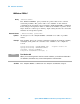
The graph on the left shows an ADC which has no non- linearity errors.
All of the voltage levels are evenly spaced producing output codes that
represent evenly spaced voltages. In the graph on the right, the voltages
are not evenly spaced with some being wider and some being narrower
than the others.
When you calibrate your Infiniium, the input to each channel, in turn, is
connected to the Aux Out connector. The Aux Out is connected to a 16- bit
digital- to- analog convertor (DAC) whose input is controlled by Infiniium's
CPU. There are 65,536 dc voltage levels that are produced by the 16- bit
DAC at the Aux Out. At each dc voltage value, the output of the ADC is
checked to see if a new digital code is produced. When this happens, a
16- bit correction factor is calculated for that digital code and this
correction factor is stored in a Calibration Look-up Table.
Figure 9 ADC Non-linearity Errors for a 3-bit ADC
Normalized Analog Input
1/8FS
2/8FS
3/8FS
4/8FS
5/8FS
6/8FS
7/8FS
FS
0
001
010
011
100
101
110
111
000
Output Digital Number
Ideal ADC Conversion
Normalized Analog Input
1/8FS
2/8FS
3/8FS
4/8FS
5/8FS
6/8FS
7/8FS
FS
0
001
010
011
100
101
110
111
000
Output Digital Number
Nonlinearity
Errors
Non-ideal ADC Conversion
FS = the full scale
voltage of the ADC