
Technical data

Mixed-Signal Oscilloscope (MSO) 5
Agilent Infiniium 9000 Series Oscilloscope Evaluation Guide 33
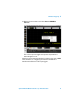
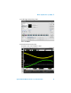
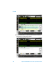
The channel 1 signal (yellow) is the filtered version of the output.
The channel 2 signal (green) shows the stair-step output of a
microcontroller-based Digital-to-Analog Converter (DAC).
Channels D0 – D7 (blue) are the input control lines to the DAC.
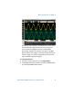
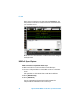
We were able to easily trigger on channel 2. However, what if we
wanted to trigger on a specific voltage instruction based on the
input to the DAC using pattern trigger?
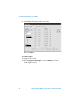
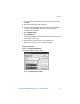
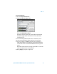
Set up digital channels:
7 From the on-screen main menu, choose Setup>Digital....
8 In the Digital Setup dialog’s Enable tab, disable the D7-D0 display
by unchecking the D
7-0
enable selection.