
User`s guide

Controls and Connectors 12
InfiniiVision Oscilloscopes User’s Guide 357
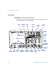
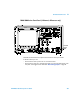
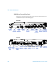
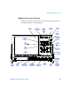
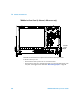
Front Panel Control and Connector Descriptions
1. Power Switch Press once to switch power on; press again to switch power off. See
page 49.
2. USB Host Port This port is for connecting USB mass storage devices or printers to
the oscilloscope.
Connect a USB compliant mass storage device (flash drive, disk drive, etc.) to store or
recall oscilloscope setup files or waveforms.
To print, connect a USB compliant printer. For more information about printing see “To
print the oscilloscope’s display” on page 245.
You can also use the USB port to update the oscilloscope’s system software when
updates are available.
You do not need to take special precautions before removing the USB mass storage
device from the oscilloscope (you do not need to “eject” it). Simply unplug the USB mass
storage device from the oscilloscope when the file operation is complete.
For more information about saving to a USB mass storage device see “Saving
Oscilloscope Data” on page 247.
3. Probe Compensation Terminals Use the signal at this terminal to match a probe’s
input capacitance to the oscilloscope channel to which it is connected. See page 77.
4. Channel Input BNC Connector Attach the oscilloscope probe or BNC cable to the
BNC connector. This is the channel’s input connector.
5. AutoProbe Interface When you connect a probe to the oscilloscope, the AutoProbe
Interface attempts to determine the type of probe and set its parameters in the Probe
Menu accordingly. On all models except 100 MHz 6000 Series. See “AutoProbe
Interface” on page 72.
CAUTION
Do not connect a host computer to the oscilloscope’s USB host port: use the device
port. A host computer sees the oscilloscope as a device, so connect the host
computer to the oscilloscope’s device port (on the rear panel). See
“Web
Interface”
on page 275.