
User`s guide

Serial Decode/Lister 10
InfiniiVision Oscilloscopes User’s Guide 331
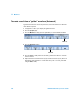
b Press the Signals softkey, and select the oscilloscope channels that you have
connected to the Rx and Tx signals. Set the trigger levels. See “UART/RS232
Trigger” on page 166 for detailed instructions.
3 Press the “Return to previous menu” (up arrow) softkey.
4 Press the Bus Config softkey.
a#Bits: Set the number of bits in the UART/RS232 words to match your device
under test (selectable from 5-9 bits).
bParity: Choose odd, even, or none, based on your device under test.
cBaud: Select the baud rate to match the signal in your device under test.
dPolarity: Select idle low or idle high to match your device under test’s state when
at idle. For RS232 select idle low.
e Bit Order: Select whether the most significant bit (MSB) or the least significant bit
(LSB) is presented after the start bit in the signal from your device under test. For
RS232 select LSB.
5 Press the “Return to previous menu” (up arrow) softkey.
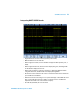
6 Press the Base softkey to select the base (hex, binary, or ASCII) in which decoded
words are displayed.
• When displaying words in ASCII, the 7-bit ASCII format is used. Valid ASCII
characters are between 0x00 and 0x7F. To display in ASCII you must select at least
7 bits in the Bus Configuration. If ASCII is selected and the data exceeds 0x7F, the
data is displayed in hex.
• When #Bits is set to 9, the 9th (alert) bit is displayed directly to the left of the ASCII
value (which is derived from the lower 8 bits).
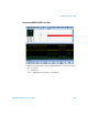
7 Optional: Press the Framing softkey and select a value. In the decode display the
chosen value will be displayed in light blue. However, if a parity error occurs the data
will be displayed in red.
NOTE
Changing the Bus Configuration settings in the Serial Decode setup also changes them in
the Trigger setup.
NOTE
In the decode display the most significant bit is always displayed on the left regardless of
how Bit Order is set.