
User`s guide


4 Triggering
122 InfiniiVision Oscilloscopes User’s Guide
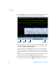
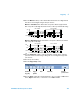
6 Press the Signals softkey to display the I
2
S Signals Menu. A diagram appears showing
WS, SCLK, and SDATA signals for the currently specified bus configuration.
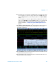
7 Connect an oscilloscope channel to the SCLK (serial clock) line in the device under
test. (If the channel is not already switched on, switch it on now, and return to this
menu by pressing [More]&Settings& Signals.)
Rotate the Entry knob to set the SCLK clock channel softkey to the SCLK channel.
As you rotate the Entry knob the SCLK label for the source channel is automatically
set and the channel you select is shown in the upper-right corner of the display next to
“I
2
S”.
8 Connect an oscilloscope channel to the WS (word select) line in the device under test,
switch the channel on, then set the WS channel softkey to that channel.
9 Connect an oscilloscope channel to the SDATA (serial data) line in the device under
test, switch the channel on, then set the SDATA channel softkey to that channel.
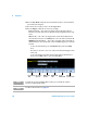
Serial clock
channel
Word Select
channel
Return to
previous menu
Serial data
channel