
User`s guide

4 Triggering
100 InfiniiVision Oscilloscopes User’s Guide
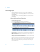
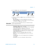
7 Press the Signals softkey to enter the CAN Signals Menu.
8 Press the Source softkey to select the channel connected to the CAN signal line.
As you repeatedly press the Source softkey (or rotate the Entry knob), the CAN label
for the source channel is automatically set and the channel you select is shown in the
upper-right corner of the display next to “CAN”.
If you have connected one of the oscilloscope’s analog source channels to the CAN
signal: Adjust the trigger level for the selected analog channel to the middle of the
waveform by turning the Trigger Level knob.
If you have connected one of the oscilloscope’s digital source channels to the CAN
signal (this applies to MSO model oscilloscopes only): Press the [D15-D0] key and
select Thresholds to set an appropriate threshold level for digital channels.
The value of the trigger level or digital threshold is displayed in the upper-right corner
of the display.
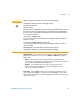
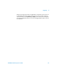
9 Press the Signal softkey and select the type and polarity of the CAN signal. This also
automatically sets the channel label for the source channel.
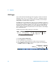
• CAN_H — The actual CAN_H differential bus
Dominant low signals:
• CAN_L — The actual CAN_L differential bus signal
• Rx — The Receive signal from the CAN bus transceiver
• Tx — The Transmit signal from the CAN bus transceiver
• Differential — The CAN differential bus signals connected to an analog source
channel using a differential probe. Connect the probe’s positive lead to the
dominant-low CAN signal (CAN_L) and connect the negative lead to the
dominant-high CAN signal (CAN_H).
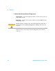
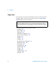
10 Repeatedly press and release the Baud softkey to set the CAN signal baud rate to
match your CAN bus signal.
Baud Rate
Signals
source
Sample
Point
Return to
previous menu
User-
defined
Baud Rate
CAN Signal
Selection