
Technical data


Verifying I
2
S Serial Bus Communication 11
Agilent InfiniiVision 7000B Series Oscilloscopes Evaluation Guide 59
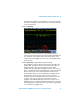
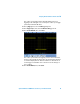
You should now see I
2
S decoding based on 8-bit words of “left” channel
and “right” channel data. Note that this might represent stereo
information in a digital audio/sound system. Let’s now set up the
oscilloscope to trigger on a specific transmitted audio data.
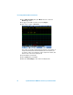
12 Press [Trigger]; then, select the I
2
S trigger mode.
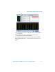
13 Press Trigger Setup to view the default I
2
S trigger condition.
Note that the default trigger condition is to trigger when the left-channel
data equals “0” (signed decimal value), and we can see that this
condition occurs when the analog waveform on channel 2 (green trace)
crosses through the 50% level of a sine wave output in either the positive
or negative direction. Let’s now set up the oscilloscope to trigger on a
specific direction of the output analog signal (increasing or decreasing
data value).
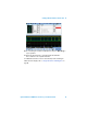
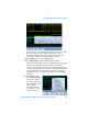
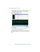
14 Press Trigger =; then,
select (Increasing Value)
as the trigger condition.
The oscilloscope should
now be triggering on +20,
which is the first
left-channel data value
captured after crossing
through -10 and +10