
Technical data


58
Agilent InfiniiVision 7000B Series Oscilloscopes
Evaluation Guide
11
Verifying I
2
S Serial Bus
Communication
The Integrated Interchip sound (I
2
S) bus is a serial bus interface standard
used for connecting digital audio devices together, such compact disc, digital
audio tape, digital sound processors, and digital TV sound. The I
2
S serial bus
is based on a 2’s complement format. The serial data channel includes both
left and right channel audio information (stereo). In addition to the serial data
signal, the I
2
S protocol also includes an explicit clock signal (SCLK) and a
word select (WS) signal. To enable I
2
S decoding, your oscilloscope must
have the I
2
S serial bus decode option (Option I2S) installed. You can verify
the installed options on your oscilloscope at [Utility] > Service > About
Oscilloscope.
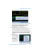
Setup
1 Connect the demo kit’s 40-pin ribbon cable from the back of the Agilent
InfiniiVision Series oscilloscope to the 40-pin connector on the demo
board.
2 Connect channel 1 probe to the CH1 test point and ground (GND).
3 Connect channel 2 probe to the CH2 test point and ground (GND).
4 Set the rotary switch on the demo board for the I
2
S signal (Mode #C).
5 Press [Default Setup].
6 Press [Auto Scale].
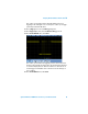
7 Set the timebase to 10.0 µs/div.
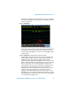
8 To turn on I
2
S decode, first press
[Serial]; then, select the I
2
S serial
decode mode.
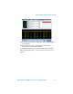
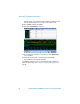
9 To define the I
2
S serial input signals,
first press Signals; then, select the
D14 input as the serial clock (SCLK) source.
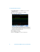
10 Next, press WS; then, select the D15 input as the Word Select source.
11 Now press SDATA; then, select the channel 1 input as the serial data
source.