
Technical data


54
Agilent InfiniiVision 7000B Series Oscilloscopes
Evaluation Guide
10
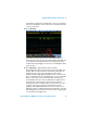
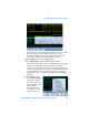
Verifying LIN Serial Bus
Communication
The LIN serial bus is another protocol that is used in many automotive
applications. The LIN protocol is more often used in less safety-critical
applications as compared to CAN automotive applications. LIN is a
single-ended bus (signal to ground) with voltage levels usually based on the
car’s battery voltage. Similar to CAN, the clock is embedded within the LIN
data signal. This bus is typically slower and lower cost than CAN technology.
Typical non-safety critical applications include seat and mirror controls. To
enable LIN decode and triggering, your oscilloscope must have the CAN/LIN
serial bus decode option (Option AMS) installed. You can verify the installed
options on your oscilloscope at [Utility] > Service > About Oscilloscope.
Setup
1 Connect the demo kit’s 40-pin ribbon cable from the back of the Agilent
InfiniiVision Series oscilloscope to the 40-pin connector on the demo
board.
2 Connect channel 1 probe to the CH1 test point and ground (GND).
3 Connect channel 2 probe to the CH2 test point and ground (GND).
4 Set the rotary switch on the demo board for the LIN signal (Mode #9).
5 Press [Default Setup].
6 Set the channel 1 vertical scale to
500 mV/div and the vertical offset to
+1.0 V.
7 Push the Trigger Level knob to set the
channel 1 trigger level to 50%.
8 Set the timebase to 1.0 ms/div.
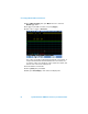
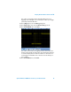
9 To turn on LIN decode, first press
[Serial]; then, select the LIN serial decode mode.
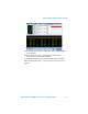
10 To set decoding for the appropriate baud rate of our demo signal, press
Settings.
11 Press Baud Rate; then, select 19.2 kb/s.