
Technical data

48
Agilent InfiniiVision 7000B Series Oscilloscopes
Evaluation Guide
9
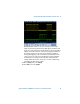
Verifying CAN Serial Bus
Communication
The Controller Area Network (CAN) bus is used in a variety of today’s auto-
motive and industrial applications. Because this bus is typically differential, it
is a very robust bus with lots of noise immunity and can be used to communi-
cate over relatively long distances between devices. Because the CAN bus is
usually a differential bus, a differential active probe is typically required.
However, the CAN signal on our demo board is a single-ended signal
(CAN_L). So for this lab, we will be using a standard high impedance passive
probe. With a CAN bus signal, there is not an explicit clock signal as there is
with I
2
C and SPI. Clocking is embedded within the CAN signal, and CAN
receivers must recover the clock based on a known baud rate. To enable CAN
decoding, your oscilloscope must have the CAN/LIN serial bus decode
option (Option AMS) installed. You can verify the installed options on your
oscilloscope at [Utility] > Service > About Oscilloscope.
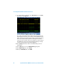
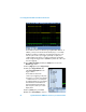
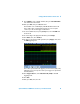
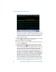
Setup
1 Connect the demo kit’s 40-pin ribbon cable from the back of the Agilent
InfiniiVision Series oscilloscope to the 40-pin connector on the demo
board.
2 Connect channel 1 probe to the CH1 test point and ground (GND).
3 Connect channel 2 probe to the CH2 test point and ground (GND).
4 Set the rotary switch on the demo board for the CAN signal (Mode #8).
5 Press [Default Setup].
6 Set the channel 1 vertical scale to
1.0 V/div and the vertical offset to
-1.0 V.
7 Push the Trigger Level knob to set
triggering on channel 1 at the 50%
level.
8 Turn on channel 2.