
Technical data

8 Verifying RS-232/UART Serial Bus Communication
46 Agilent InfiniiVision 7000B Series Oscilloscopes Evaluation Guide
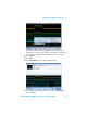
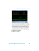
You should now see the encoded message: “Agilent MSOs RRR #1”. In
addition, you may notice that the last decoded byte (1) is occasionally
flashing in red. This is an indication of an infrequent parity error. Let’s
now set up the oscilloscope to trigger specifically on a parity error
condition. But because this error condition is infrequent, we will first
need to change the trigger mode to NORMAL to prevent the oscilloscope
from auto triggering.
16 Press [Mode/Coupling] and then press Mode twice to select the
Normal trigger mode.
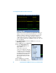
17 Press [Trigger]; then, press Trigger Setup.
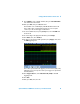
18 Next, press Trigger Tx Data; then,
select Rx or Tx Parity Error as the
trigger condition.
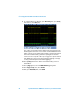
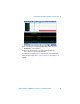
You should now see that the
oscilloscope is triggering on the parity
error (red “1”) at center-screen and the
“1” ASCII character is constantly red
(no longer flashing). Let’s now analyze
transmitted and received data both
before and after this particular error
byte using the oscilloscope’s “lister”
display mode.
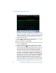
19 Press [Serial]; then, press Lister.
20 Next, press Lister Display to turn it on.